Compressible cargo bar

a cargo bar and expandable technology, applied in the direction of cargo supporting/securing components, load transportation vehicles, transportation items, etc., can solve the problems of unsatisfactory incorporated springs, considerable expense and complexity, and the addition of spring components, etc., to achieve the effect of considerable expense and complexity

Inactive Publication Date: 2006-03-09
PEERLESS CHAIN COMPANY
View PDF4 Cites 7 Cited by
  • Summary
  • Abstract
  • Description
  • Claims
  • Application Information

AI Technical Summary

Benefits of technology

[0006] A previously proposed solution to this problem is to incorporate metal springs into the cargo bar ends i.e., between the rigid end of the bar and the elastameric pad. Such incorporated springs has not been deemed satisfactory. The spring components add considerable expense and complexity. Also, the resistive force of the spring must be reliably sufficient to produce the necessary gripping force and yet have a predictable release to avoid buckling of the bar and / or opposing walls. This criteria has not been satisfactorily achieved by existing metal spring mechanism and has prompted the present invention.

Problems solved by technology

Such incorporated springs has not been deemed satisfactory.
The spring components add considerable expense and complexity.

Method used


Image

  • Compressible cargo bar
  • Compressible cargo bar
  • Compressible cargo bar

Examples


Embodiment Construction

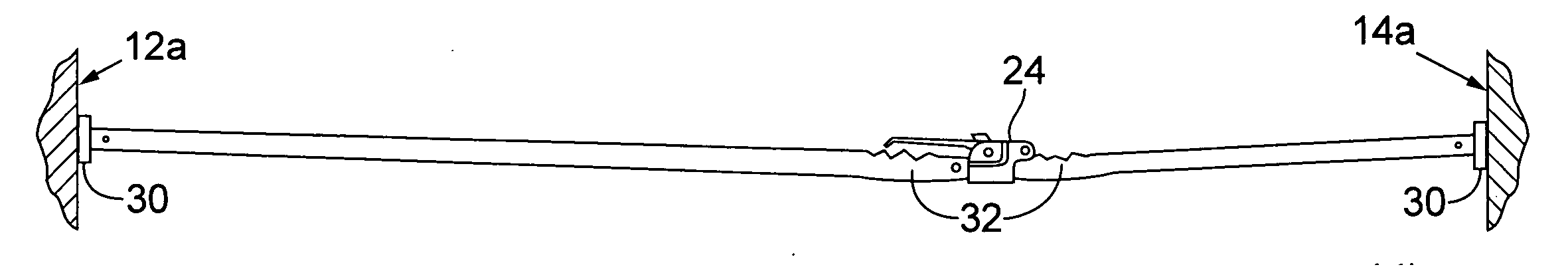
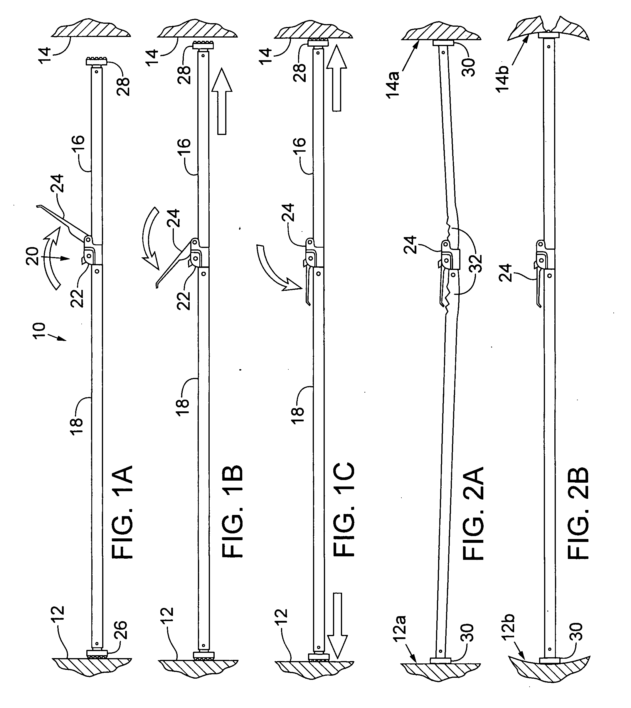
[0014]FIGS. 1A, 1B and 1C illustrate the application of a cargo bar 10 being applied between opposing side walls 12, 14. The cargo bar 10 includes telescoping square tubes having a smaller sized tube 16 slideable into a larger sized tube 18. A locking device 20 is of conventional design and includes a releasable ratchet wheel 22 and hand lever 24. Ratchet teeth formed on the small tube are engaged by the ratchet wheel and as the lever 24 is manually pivoted e.g., from the position of FIG. 1A to the position of 1B and then to FIG. 1C, the bar length is extended (compare the bar length of FIG. 1A to that of FIG. 1C).

[0015] In operation, the lever 24 is pivoted to the forward most position (FIG. 1A) where the teeth of the wheel 22 disengage from the teeth of tube 16. The tube section 16 is manually pulled to extend the bar length until the ends substantially span the distance between walls 12, 14, and then the handle 24 is pivoted to force pressure engagement of both bar ends 26, 28 a...


PUM


Abstract

A cargo bar for retaining loads in a cargo container having opposing side walls. The cargo bar includes telescoping sections and end devices at the opposed ends of the cargo bar. The end devices are elastameric and absorb excessive forces that induce pressure grip extension of the telescoping sections.

Description

RELATED APPLICATION [0001] The present invention is a Non-Provisional Application of Provisional Application No. 60 / 607,721 filed Sep. 7, 2004 entitled “Compressible Foot Member for Friction Type Cargo Stabilization Devices,” claims priority to said provisional application, and incorporates its specification in its entirety by reference.FIELD OF THE INVENTION [0002] This invention relates to the use of extendable cargo bars that are forcibly extended between opposing wall surfaces for pressure induced grip retention of the bars to the walls. BACKGROUND OF THE INVENTION [0003] The use of cargo bars for sectioning off cargo loads is well known. Typically, a cargo carrying truck box has opposed side walls and often it happens that a partial load needs to be transported and that cargo load likely needs to be held in place in the truck box. Cargo bars are elongate extendable / contractible members (e.g., telescoping square tubes) having end pads that can be forcibly pressed against the sid...

Claims


Application Information

Patent Timeline
Patent Type & Authority Applications(United States)
IPC IPC(8): B61D45/00
CPCB61D45/001B60P7/15
Inventor SCOTT, GARY M.
Owner PEERLESS CHAIN COMPANY
Why Eureka
Try Eureka