
Axial piston engine with integrated filling pump

a technology of axial piston engine and filling pump, which is applied in the direction of liquid fuel engine, rotary/oscillating piston pump components, machines/engines, etc., can solve the problems of increasing wear, failure of the filling pump, and deformation of the sha

Active Publication Date: 2006-03-09
DANFOSS POWER SOLUTIONS INC
View PDF4 Cites 14 Cited by
  • Summary
  • Abstract
  • Description
  • Claims
  • Application Information

AI Technical Summary

Benefits of technology

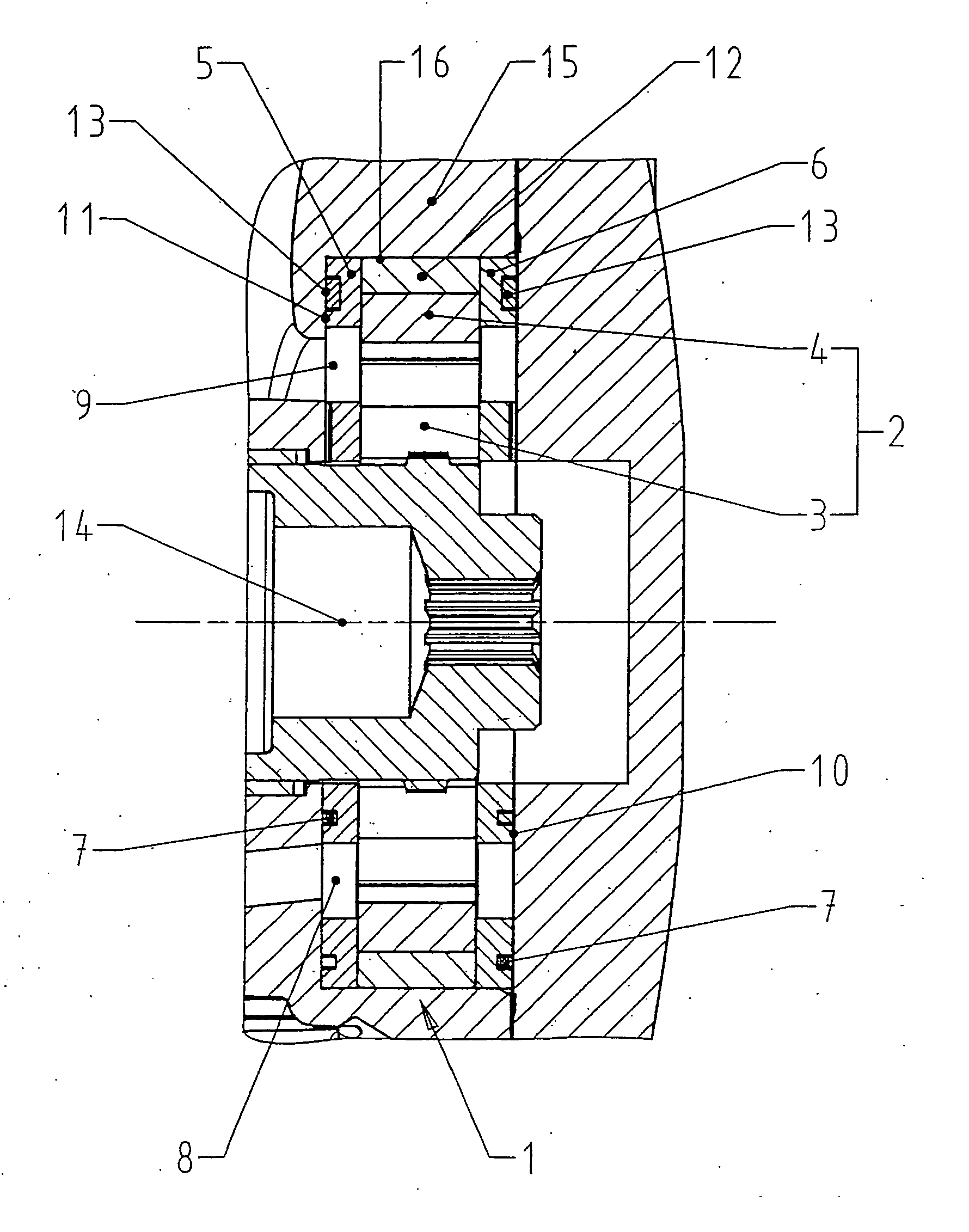
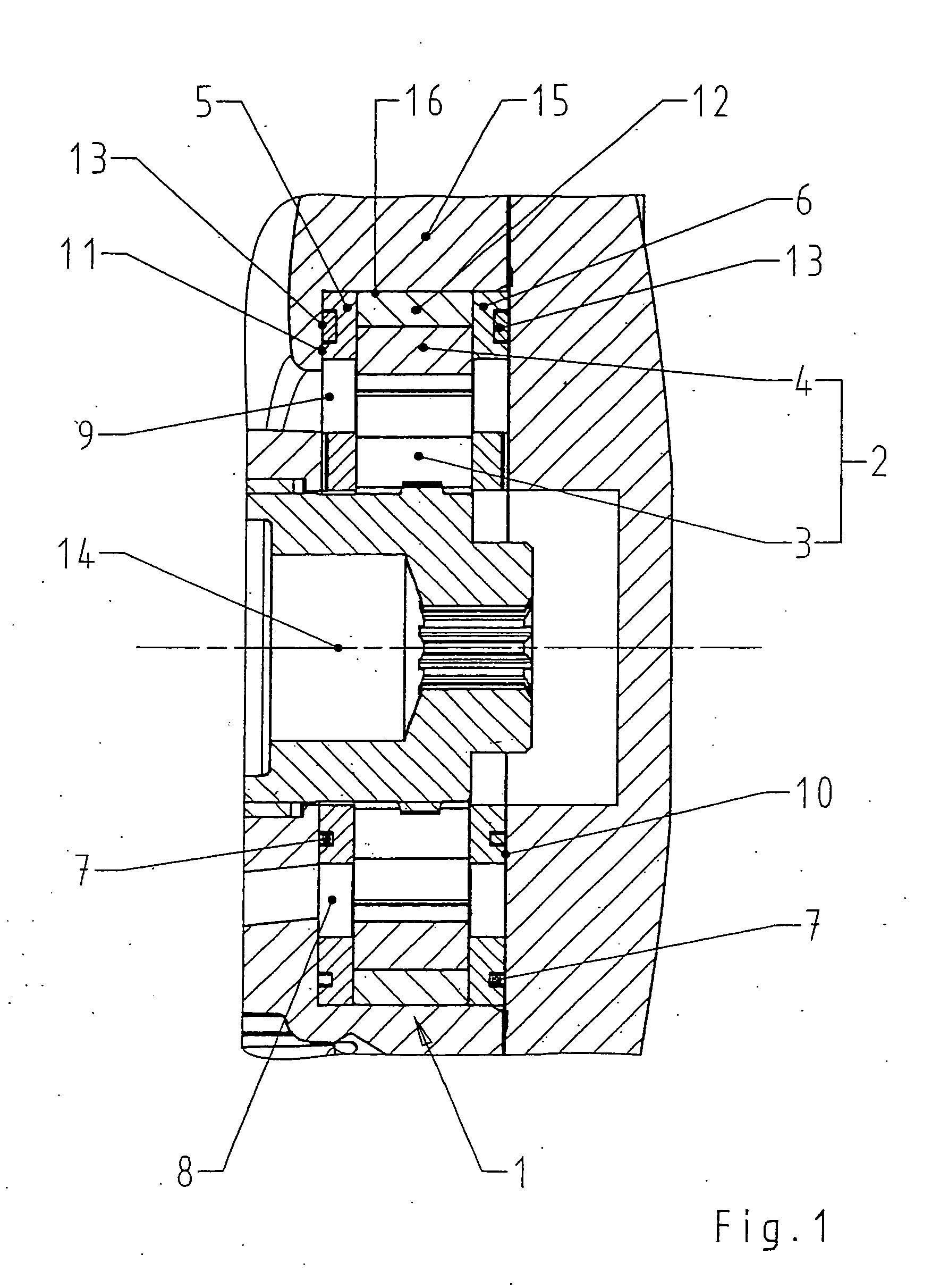
[0008] According to the invention, a filling pump is integrated in a receiving bore in the axial piston engine, which filling pump comprises a gerotor set with an externally toothed inner ring and an internally toothed outer ring and also an inner thrust plate and an outer thrust plate which enclose the gerotor set between them. On their surface facing away from the gerotor set, the thrust plates are in each case supported via a pressure field seal in such a way on the housing walls axially enclosing the filling pump that lateral play in the form of axial mobility of the filling pump is guaranteed. In this connection, the pressure field seals surround in each case at least one pressure field region formed in the thrust plates.
[0010] It is advantageous if the diameter of the receiving bore is dimensioned to be slightly larger than the outside diameter of the bearing ring, because the filling pump thus has a radial play and can accordingly avoid radial constraining forces.

Problems solved by technology

All constructions have essentially two problems to contend with: on the one hand, the unavoidable operating forces acting on the shaft lead to the latter being shifted out of its optimum position, elastic deformations of the shaft moreover arising, owing to which constraining forces are in each case exerted on the filling pump.
These constraining forces caused by shaft shifts and shaft deformations have to be kept away from the filling pump to the greatest extent possible as otherwise they also load its parts radially and axially, displace them and possibly even misalign them, which results in increased wear and can lead to failure of the filling pump.
This results in manufacturing being highly complex and especially difficult to effect in practice when these walls are to be fashioned in the pump housing itself.
The construction requires a great deal of construction space and is expensive.

Method used


Image

  • Axial piston engine with integrated filling pump
  • Axial piston engine with integrated filling pump
  • Axial piston engine with integrated filling pump

Examples


Embodiment Construction

[0020]FIG. 1 shows the filling pump 1 according to the invention, which is built into the end housing 15 of an axial piston engine. The filling pump 1 comprises a gerotor set 2 with an externally toothed inner ring 3 and an internally toothed outer ring 4, which rings are driven by the main shaft 14 of the axial piston engine. The gerotor set 2 is mounted in a bearing ring 12 which surrounds the gerotor set 2 externally and is inserted into a receiving bore 16 of the axial piston engine. In this connection, the bearing ring 12 surrounds the internally toothed outer ring 4 of the gerotor set 2 and thus forms the radial bearing of the filling pump.

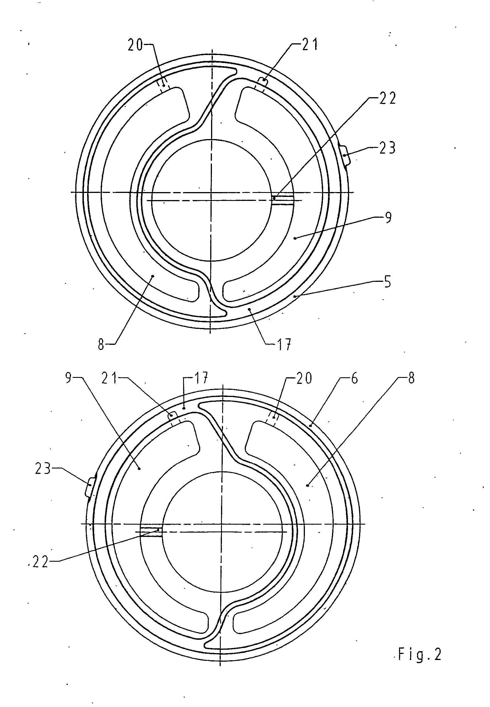
[0021] Arranged on the two sides of the gerotor set 2 and of the bearing ring 12 are an inner thrust plate 5 and an outer thrust plate 6 with kidney-shaped suction and pressure openings 8, 9, which rings have pressure field seals 7, 13 on their sides facing away from the gerotor set. In this connection, the pressure field seal 7 surrounds, ...


PUM


Abstract

The invention relates to an axial piston engine with a filling pump integrated in a receiving bore of the axial piston engine, which filling pump comprises a gerotor set with an externally toothed inner ring and an internally toothed outer ring and also an inner thrust plate and an outer thrust plate. The two thrust plates enclose the gerotor set between them and, on their surfaces facing away from the gerotor set, are in each case supported via a pressure field seal, which surrounds the pressure field regions formed in the thrust plates, in such a way on the housing walls axially enclosing the filling pump that lateral play in the form of axial mobility of the filling pump is guaranteed.

Description

BACKGROUND OF THE INVENTION [0001] The invention relates to an axial piston engine with a filling pump integrated in a receiving bore of the axial piston engine and the features according to Claim 1. [0002] To compensate for internal leakage losses and the oil quantities deliberately taken out for cooling and for filtering, closed-circuit hydraulic pumps require what is known as a filling pump, which is as a rule attached to the end housing or integrated into it as an auxiliary pump. [0003] Various types of pump can be used as a filling pump. Internal gear pumps, for example, which offer the advantage that the main shaft of the axial piston engine can be guided through the filling pump even in the case of a great shaft diameter, the main shaft at the same time driving the filling pump as well, are suitable. The drive of the filling pump can also be designed in such a way that the filling pump has its own shaft with separate bearing, which is in turn driven by the main shaft. [0004] ...

Claims


Application Information

Patent Timeline
IPC IPC(8): F01C1/02
CPCF04C15/0026F04C2/102
Inventor THOMS, REINHARDTFIEBING, CARSTEN
Owner DANFOSS POWER SOLUTIONS INC
Learn More