
Adjustable bed

Inactive Publication Date: 2006-03-16
INVACARE CORP
View PDF20 Cites 16 Cited by
  • Summary
  • Abstract
  • Description
  • Claims
  • Application Information

AI Technical Summary

Benefits of technology

The present invention is about an adjustable bed with a special feature called a universal bed end. This bed end can be used at either end of the bed and can be connected with an existing motor drive assembly. The bed end has a gear box with two input shafts that can be covered by a movable cover. The bed end also has a frame with drain openings for draining water and an end cap that helps keep the bed end cover in a curved shape. The technical effect of this invention is that it allows for easy customization and flexibility in the use of the bed end, making it more comfortable and user-friendly.

Problems solved by technology

This results in the need to manufacture and store two different kinds of bed ends, and can cause mistakes when delivering and setting up a bed in a patient's home.

Method used


Image

  • Adjustable bed
  • Adjustable bed
  • Adjustable bed

Examples


Embodiment Construction

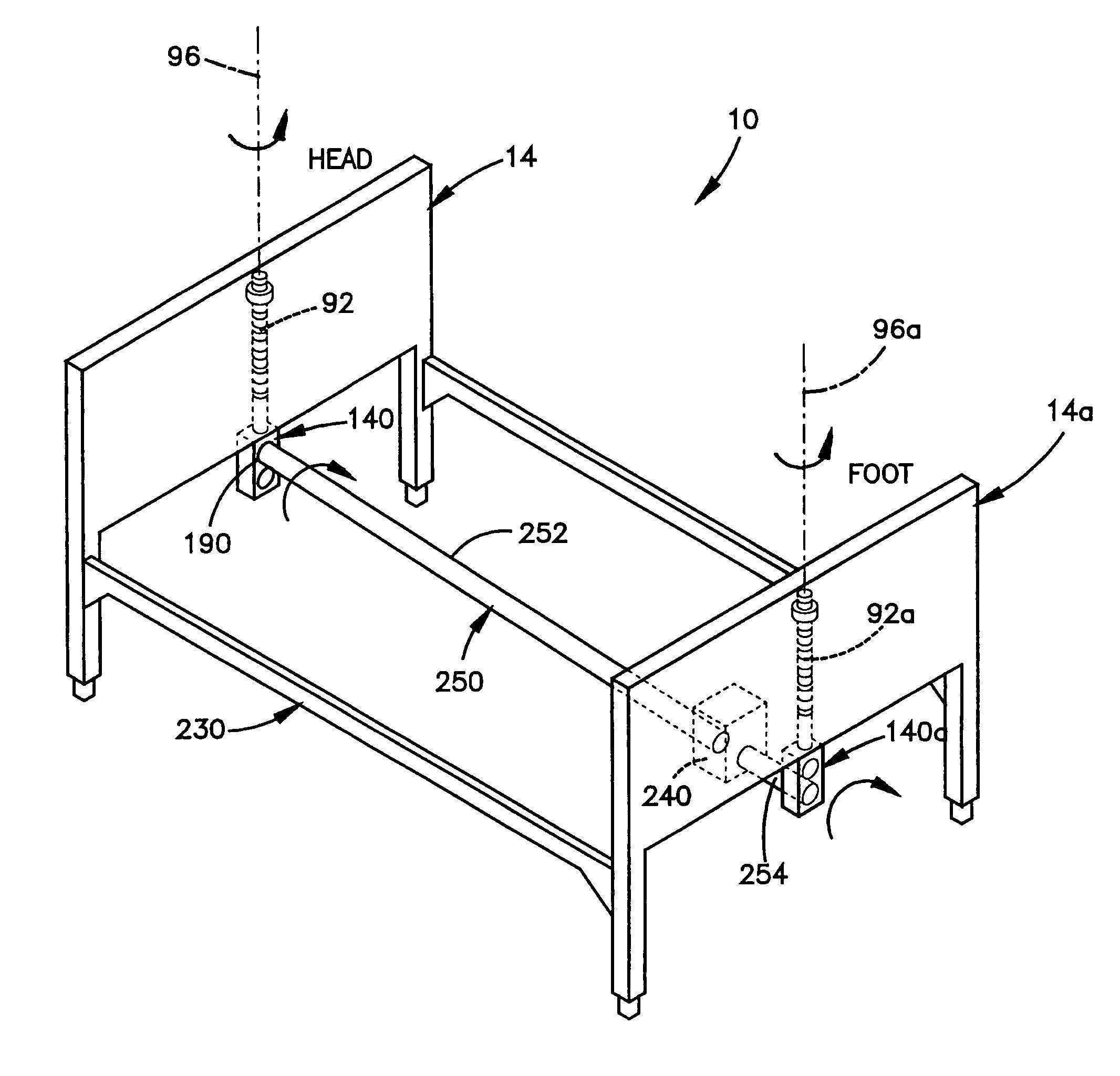
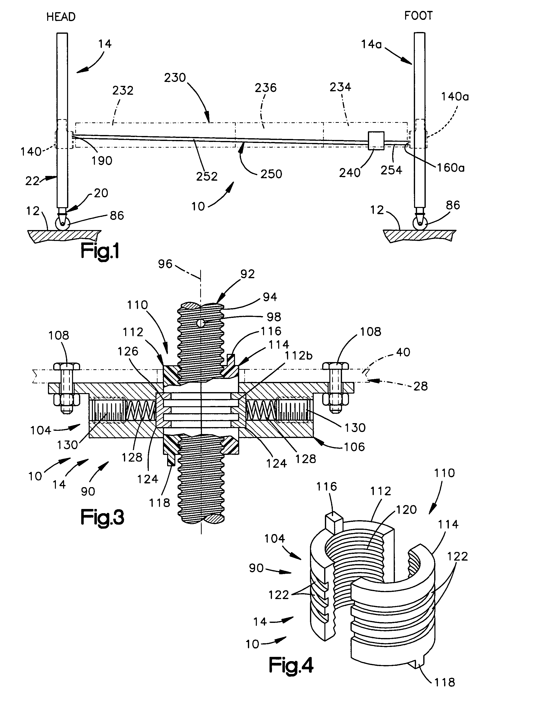
[0040] The present invention relates to adjustable beds. In particular, the present invention relates to a bed having a bed spring or other portion that is vertically adjustable, for example, for use in home health care. As representative of the present invention, FIG. 1 illustrates one embodiment of a bed 10. The bed 10 is illustrated as being placed on a floor 12.

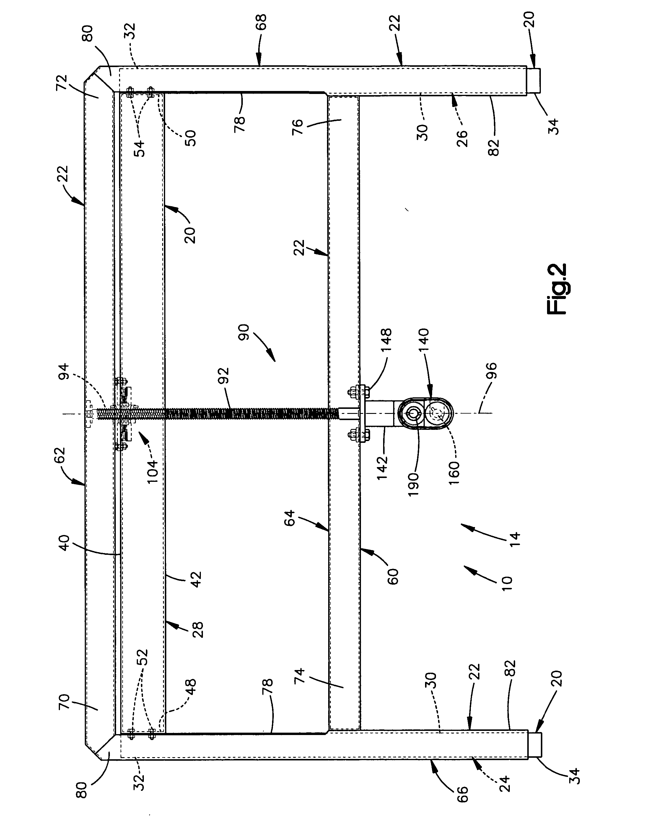
[0041] The bed 10 includes a bed end 14 that is located at the head end of the bed. The bed 10 also includes a bed end 14a that is located at the foot end of the bed. The bed end 14 is referred to herein as the “head end” of the bed 10. The bed end 14a is referred to herein as the “foot end” of the bed 10. The head end 14 of the bed 10 is identical to, and interchangeable with, the foot end 14a of the bed, as is discussed in more detail below.

[0042] The head end 14 of the bed 10 (FIG. 2) includes a fixed portion 20 and a movable portion 22. The fixed portion 20 of the head end 14 is that portion of the head end 14 that ...


PUM


Abstract

An adjustable bed includes a universal, or interchangeable, bed end that can be used at either end of the bed and can be connected with an existing motor drive assembly. The bed end may include a gear box having first and second input shafts that are selectively covered by a movable cover. The bed end may include a frame having drain openings for draining water from the bed end when the bed end is washed. The bed end may also include an end cap that is fastened to the frame in a unique manner, and that helps to maintain a panel of the bed end cover in a curved or bowed configuration.

Description

RELATED APPLICATIONS [0001] This application is a continuation in part of U.S. application Ser. No. 10 / 280,927, filed Oct. 25, 2002, titled ADJUSTABLE HEIGHT BED.TECHNICAL FIELD [0002] The present invention relates to an adjustable bed. In particular, the present invention relates to a bed having a bed spring or other portion that is vertically adjustable, for example, for use in home health care. BACKGROUND OF THE INVENTION [0003] Adjustable beds are often used in home health care. Such beds typically include a height adjustment mechanism that is operable to raise or lower the bed spring. The height adjustment mechanism may be manual or electric. A manual mechanism uses a hand crank to operate a gearbox to raise and lower the bed spring. An electric mechanism uses an electric motor that rotates a drive shaft or drive tube. The drive shaft is connected with gearboxes that face inward on the respective bed ends, that is, toward the opposite end.. When the motor is actuated, rotationa...

Claims


Application Information

Patent Timeline
Patent Type & Authority Applications(United States)
IPC IPC(8): A47C31/00A47C19/04A61G5/04A61G7/012
CPCA47C19/045Y10T74/2186A61G7/012
Inventor SNYDER, STEVENLOEWENTHAL, HOWARDSPRIEGEL, ANDREWGOERTZEN, GEROLDPUCKETT, ROBERTWYSOCKI, KEVIN
Owner INVACARE CORP
Learn More