Low temperature cooler

Inactive Publication Date: 2006-03-16
SHALLMAN RICHARD W +1
View PDF18 Cites 85 Cited by
  • Summary
  • Abstract
  • Description
  • Claims
  • Application Information

AI Technical Summary

Benefits of technology

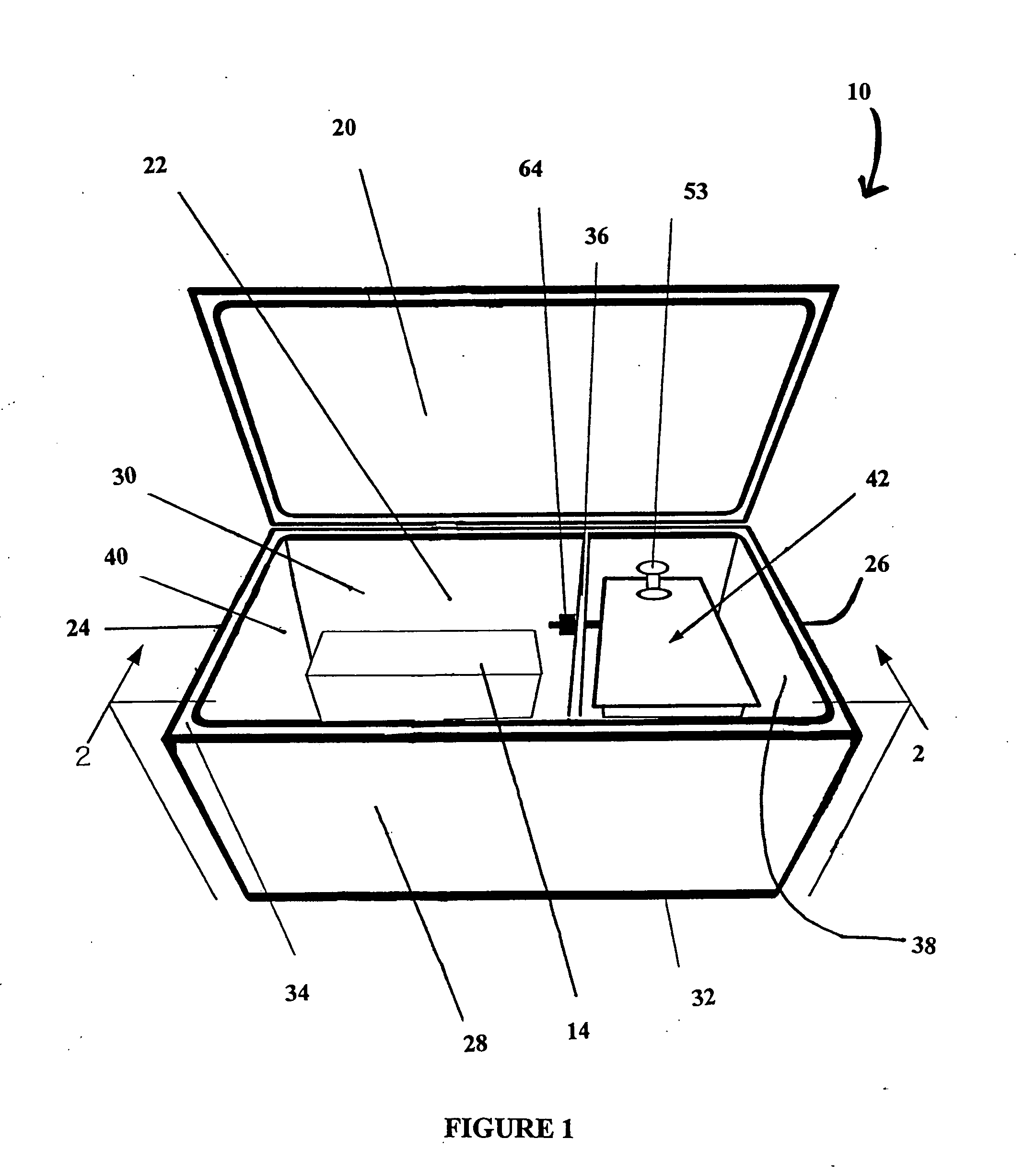
[0014] The advantages of the invention are several. First, the invention allows the temperature of the storage compartment to be kept at a specific temperature. Second, the invention allows the product in the storage compartment to be separated from the cooling agent so as not to be immersed in it. Third, the invention allows much colder temperatures to be achieved in the storage compartment than is currently possible with most disposable coolers. Fourth, the cooler is much more economically constructed than other cooling units achieving similar temperatures

Problems solved by technology

However, while the construction of portable coolers may vary greatly, the means of cooling items stored within them does not.
When the cooling agent is ice, this arrangement can lead to waterlogged products, as well as a large volume of water when the ice melts.
Consequently, there exists a dilemma between maintaining the product at the lowest temperature and keeping the products dry.
As may be appreciated, the use of portable coolers comprising liquid cooling units is neither economical nor disposable.
The units described above, using dry ice a

Method used


Image

  • Low temperature cooler
  • Low temperature cooler
  • Low temperature cooler

Examples


Example

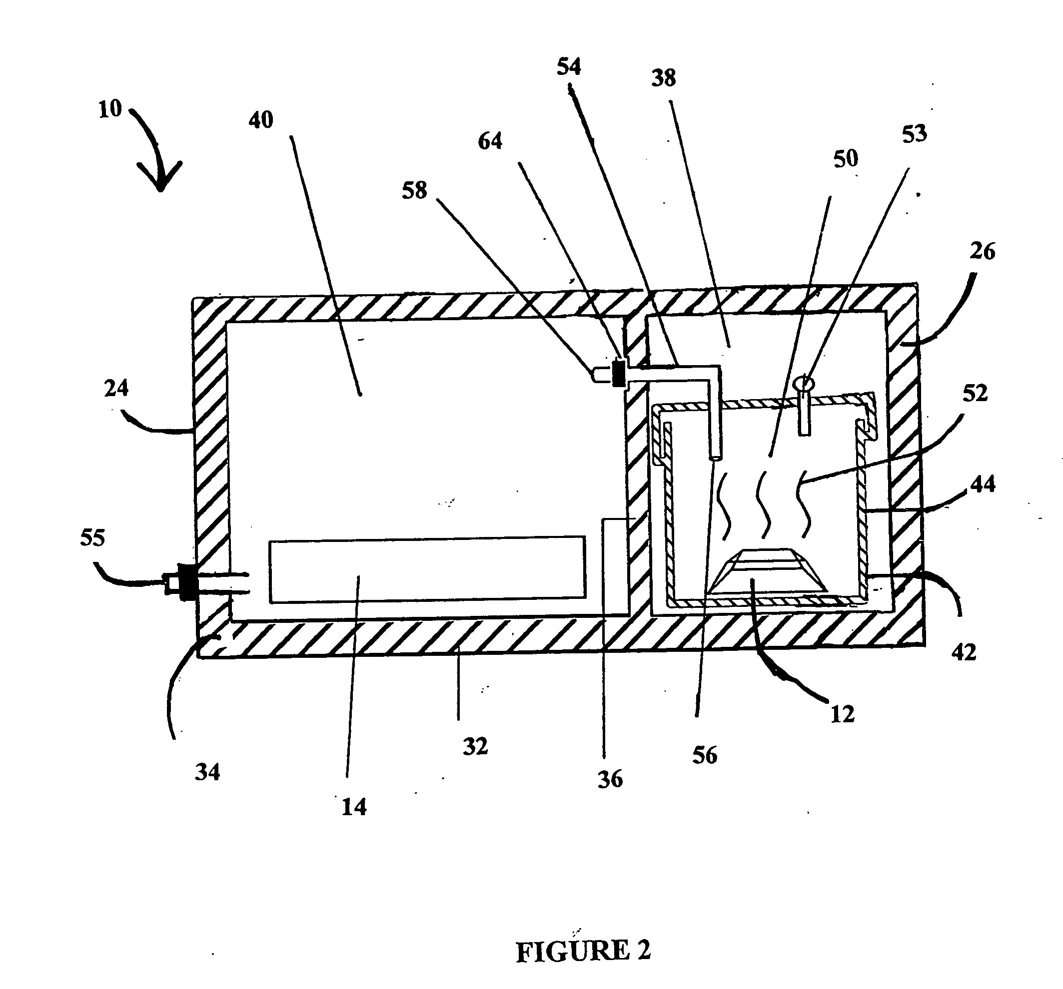
[0034] Referring again to FIG. 3, a first embodiment of the temperature-regulating valve 64 can be seen. In this embodiment, the temperature-regulating valve 64, referred to as a “Donut” valve, comprises an insulation layer 68 around the coolant tube 54 to prevent conduction from prematurely freezing the temperature-regulating valve 64. The temperature-regulating valve 64 surrounds the coolant tube 54 and may be encased in a flexible membrane, such as plastic (not shown). In this embodiment, the temperature-regulating valve 64 contains a fluid and acts as a membrane through which the vapor 52 passes. As discussed previously, the fluid can be water. As the fluid in the “donut” temperature-regulating valve 64 freezes, it compresses the coolant tube 54 and discontinues the flow of the coolant 12 from the coolant chamber 38 to the storage compartment 40 via the opening in the internal wall 36.

Example

[0035] Referring now to FIG. 4, a second embodiment of the temperature-regulating valve 64 is shown. In this embodiment, the temperature-regulating valve 64, in the form of a “Pincer” valve, comprises a base cylinder 72. The base cylinder 72 includes a first closed end 74, sides 76 and a second open end 78. Attached to the first closed end 74 is the first pincer 80, which includes a base arm 82, an extension arm 84 and a cross arm 86.

[0036] The temperature-regulating valve 64 also includes a nested sliding cylinder 88. The sliding cylinder 88 includes a first closed end 90, sides 92 and a second open end (not shown). The sliding cylinder 88 is designed to be slidably nested with the open end 78 of the base cylinder 72. Attached to the first closed end 90 of the nested sliding cylinder 88 is a second pincer 94, which also includes a base arm 96, an extension arm 98 and cross arms 100. Within the base cylinder 72 and sliding cylinder 88 is a membrane-filled expansion fluid sac 104, f...


PUM


Abstract

The invention is directed to a low-temperature cooler using dry ice as a cooling agent. The cooler has two compartments, one for the dry ice and one for chilled storage. The cooler self-regulates via an aqueous filled temperature-regulating valve to maintain a desired temperature in the storage compartment such that the products stored therein are stored at an optimum temperature. Upon achieving a predetermined temperature in the storage compartment, the valve closes, thereby maintaining the predetermined temperature in the storage compartment.

Description

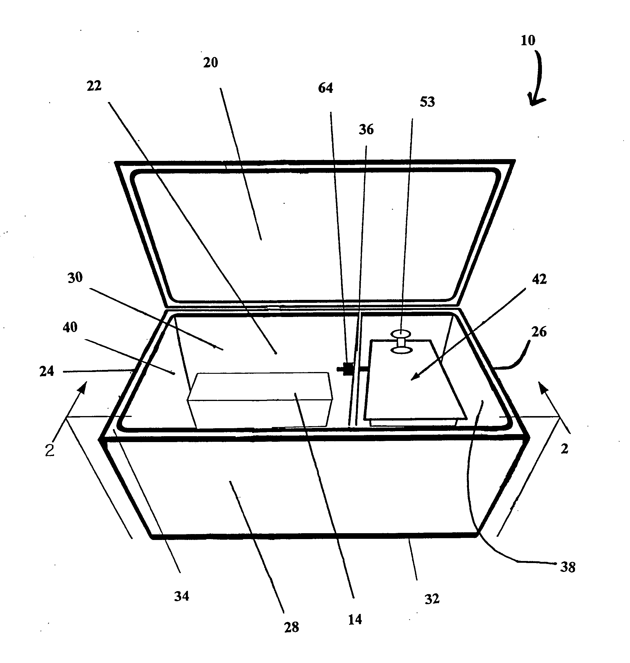
FIELD OF THE INVENTION [0001] The invention is generally directed to a portable cooler for storing and containing perishable items for transport. The invention is more specifically directed to a portable cooler comprising a first compartment for cooling and a second compartment for storage. A self-regulating valve acts to allow entry of cooling vapor from the coolant compartment into the storage compartment until a desired temperature in the storage compartment is reached. DESCRIPTION OF THE PRIOR ART [0002] Portable coolers have become ubiquitous in modern culture. As personal transport has become commonplace in society, so too has society's desire to take their portable coolers, containing perishable products, with them. While some portable coolers are quite sophisticated and made of expensive material, others are very simple, disposable coolers made of inexpensive polymer foam or other insulated material. However, while the construction of portable coolers may vary greatly, the m...

Claims


Application Information

Patent Timeline
IPC IPC(8): F17C9/02F25C1/00F25D3/12F17C13/00F25B21/00
CPCF25D3/14F25D3/107
Inventor SHALLMAN, RICHARD W.SHALLMAN, ERIK C.
Owner SHALLMAN RICHARD W
Why Eureka
Try Eureka