Universal KE projectile, in particular for medium caliber munitions

Active Publication Date: 2006-03-16
RWM SCHWEIZ
View PDF14 Cites 10 Cited by
  • Summary
  • Abstract
  • Description
  • Claims
  • Application Information

AI Technical Summary

Problems solved by technology

Known types of munitions frequently do not have a penetrating effect against modern targets such that the munition type is in a position to claim that it can bring a large destructive power to a target.
Furthermore, the destructive power is aided additionally by the asso

Method used


Image

  • Universal KE projectile, in particular for medium caliber munitions
  • Universal KE projectile, in particular for medium caliber munitions
  • Universal KE projectile, in particular for medium caliber munitions

Examples


Embodiment Construction

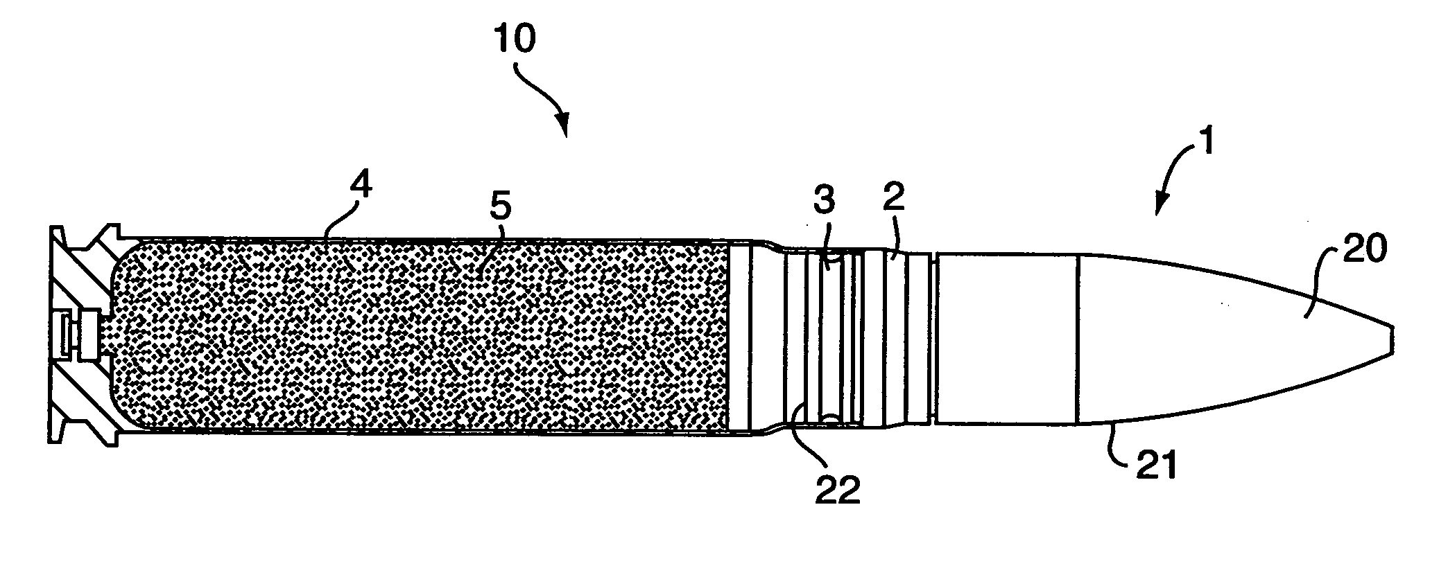
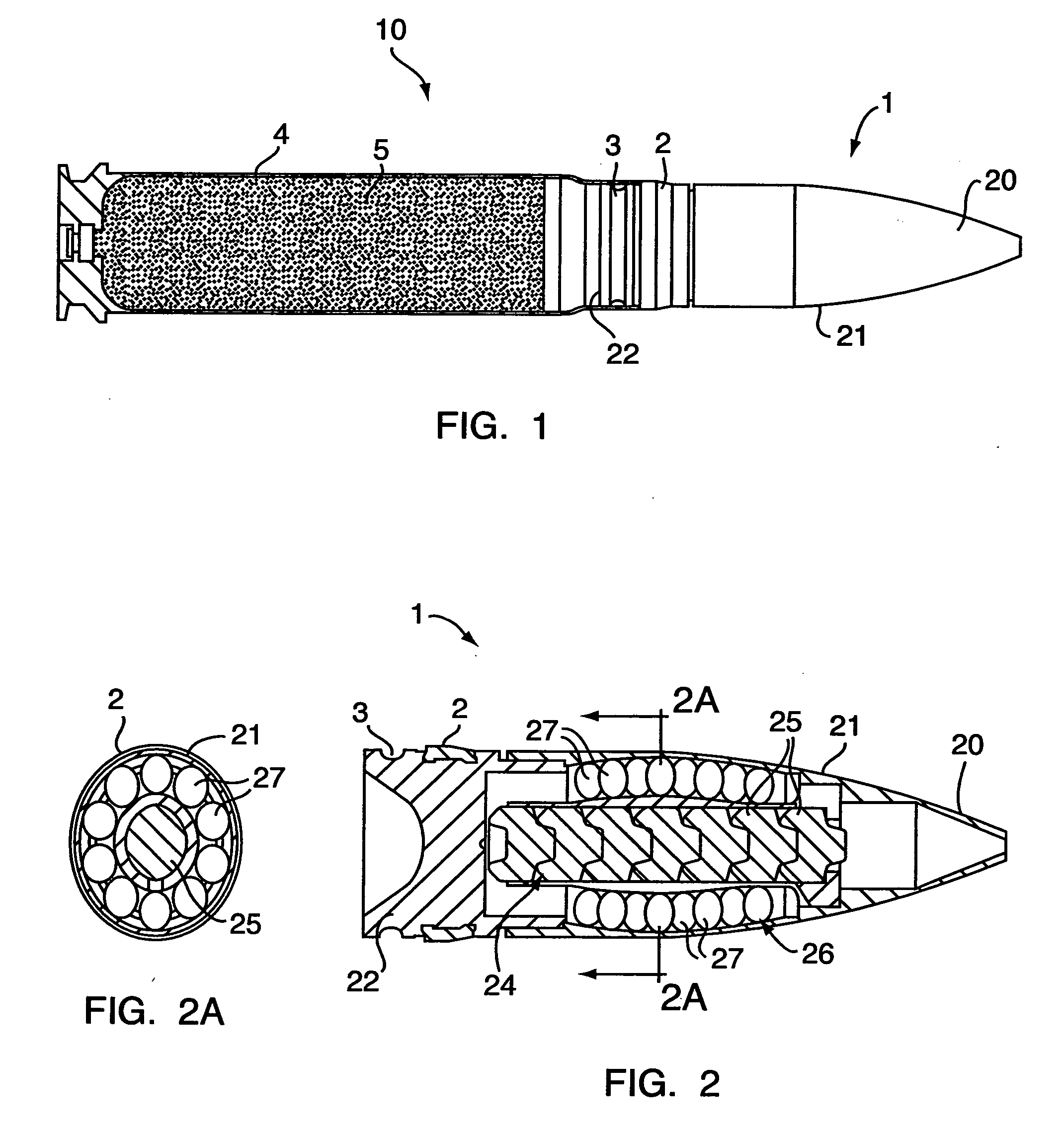
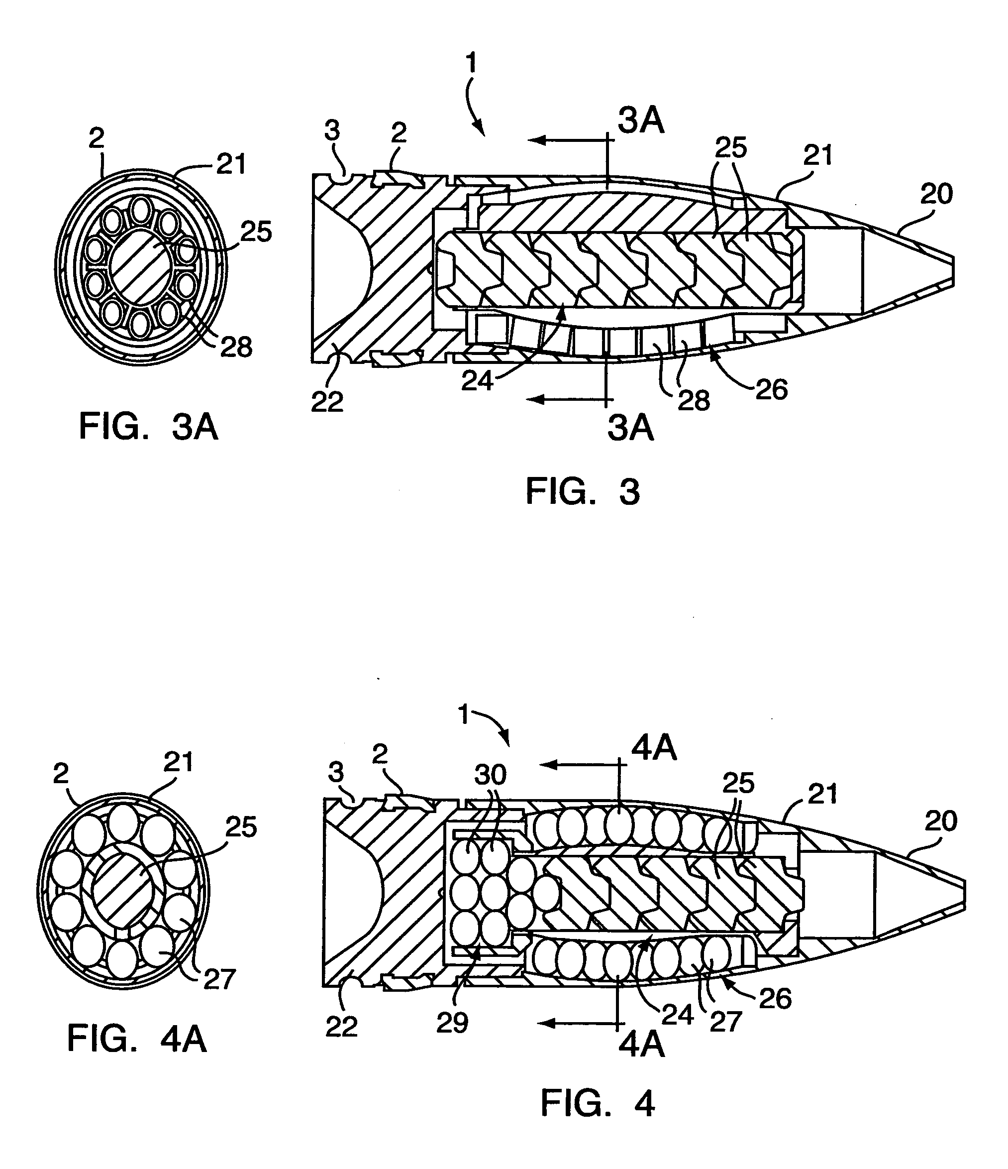
[0020] The projectile 1, a universal (multi-purpose) KE projectile, is formed with a projectile tip 20, a projectile sleeve 21 as well as a tail end 22. A central penetrator designated 24, which is preferably composed of frangible pellets 25, can also be a single piece, and in many cases also can be designated as the projectile core. An external penetrator designated 26 consists of a ball-shaped 27, possibly also cylinder-shaped 28 (cylindrical or the like and / or cube-shaped and / or block like) ductile heavy metal (FIG. 3) which here is designated as sub-projectiles 27, 28. A final penetrator 29, preferably the end of the frangible central penetrator 24, consists in one further variant accordingly to FIG. 4 likewise of ball shaped or cylinder shaped ductile heavy metal 30 which also is designated as a sub-projectile.

[0021] The exterior projectile 26 preferably has in all embodiments a curve shape or correspondingly a banana shape or design in order to preferably accomplish a bucklin...


PUM


Abstract

It is proposed to combine the cascade effect of frangible pellets with sub-projectiles made of ductile heavy metal, that is, to produce a munition in which the advantages of for example frangible pellets of a central penetrator are combined with the advantages of the ductile heavy metal in an external penetrator\whereby an improved performance on various targets is achieved along with deeper impact speeds.

Description

CROSS REFERENCE TO RELATED APPLICATIONS [0001] The priority of German Patent Application DE 10 2004 005 042.2 filed Jan. 30, 2004 and U.S. Provisional Patent Application filed Mar. 20, 2004 is claimed, and the disclosure of both the German and U.S. Provisional Patent Applications are incorporated by reference.FIELD OF THE INVENTION [0002] The invention relates to a universal-KE (kinetic energy) projectile, a method for manufacturing the projectile as well as its application. BACKGROUND OF THE INVENTION [0003] Known types of munitions frequently do not have a penetrating effect against modern targets such that the munition type is in a position to claim that it can bring a large destructive power to a target. This power is achieved by means of a large splintering effect in radial directions as well as in the direction of the target. Furthermore, the destructive power is aided additionally by the associated blast. [0004] A conventional projectile as well as its method of manufacture i...

Claims


Application Information

Patent Timeline
IPC IPC(8): F42B12/32
CPCF42B12/32F42B12/06
Inventor BURRI, JAKOB
Owner RWM SCHWEIZ
Why Eureka
Try Eureka