
Air spring mount with snap-in attachment

a technology of air springs and mounting brackets, which is applied in the direction of shock absorbers, mechanical equipment, transportation and packaging, etc., can solve the problems of inability to control the deflection of fingers toward the mounting stud, the snap-in configuration requires more expensive tooling, and the inability to provide lateral resistance to opposing fingers, etc., to achieve convenient installation and reduce manufacturing costs , the effect of increasing the resistance to inadvertent detachmen

Inactive Publication Date: 2006-03-16
VEYANCE TECH
View PDF7 Cites 36 Cited by
  • Summary
  • Abstract
  • Description
  • Claims
  • Application Information

AI Technical Summary

Benefits of technology

[0005] The present invention provides an air spring mount having a snap-in-place attachment that facilitates ready installation while providing increased resistance to inadvertent detachment of the mount from a mounting plate and minimizing manufacturing costs. In one embodiment, an air spring mount according to the present invention includes at least one support plate and an elastomeric member coupled to the support plate to define a pressurizable chamber. A snap-in-place attachment is disposed on the support plate and includes a mounting stud projecting substantially perpendicularly from the support plate. Three resilient fingers project from the support plate, adjacent the mounting stud, and are spaced peripherally around the stud. The fingers have radially outwardly projecting barbs disposed on terminal ends of the fingers for engaging a mounting bracket after the stud and resilient fingers of the attachment have been inserted through a hole formed in the mounting bracket.

Problems solved by technology

While this type of mount is easy to install, the oppositely disposed fingers do not provide resistance to lateral loading of the mount in a direction perpendicular to the aligned fingers.
Such loading may be due to misalignment of components or to an overturning moment applied to the mounted structure during aggressive maneuvering or crash conditions.
This particular snap-in configuration requires more expensive tooling due to the increased number of fingers needed for the attachment.
Another drawback of conventional snap-in-place mounting attachments for air spring mounts is that control of the deflection of the fingers toward the mounting stud is typically unrestricted.
This can cause severe loading of the fingers and can lead to fracture or cause the mount to pop out of the mounting bracket.

Method used


Image

  • Air spring mount with snap-in attachment
  • Air spring mount with snap-in attachment
  • Air spring mount with snap-in attachment

Examples


Embodiment Construction

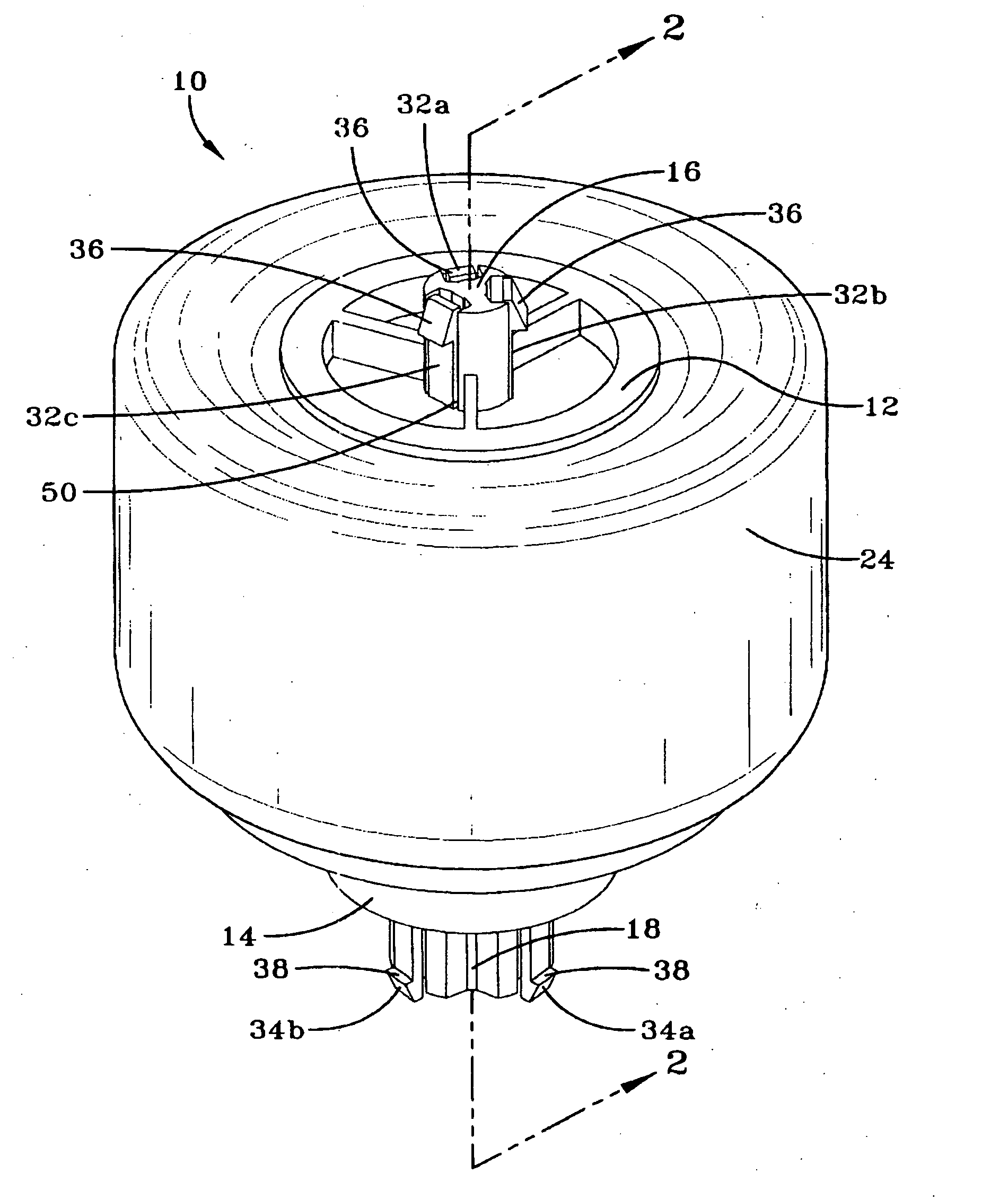
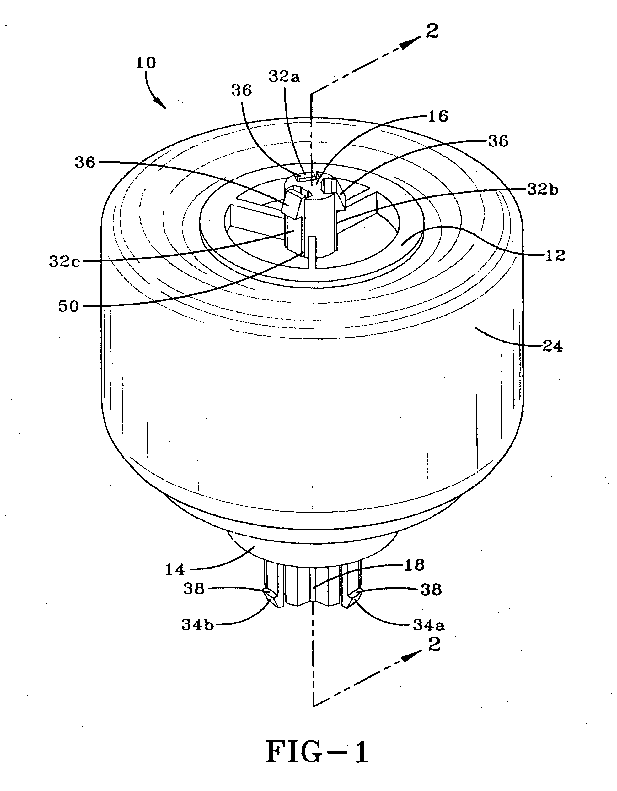
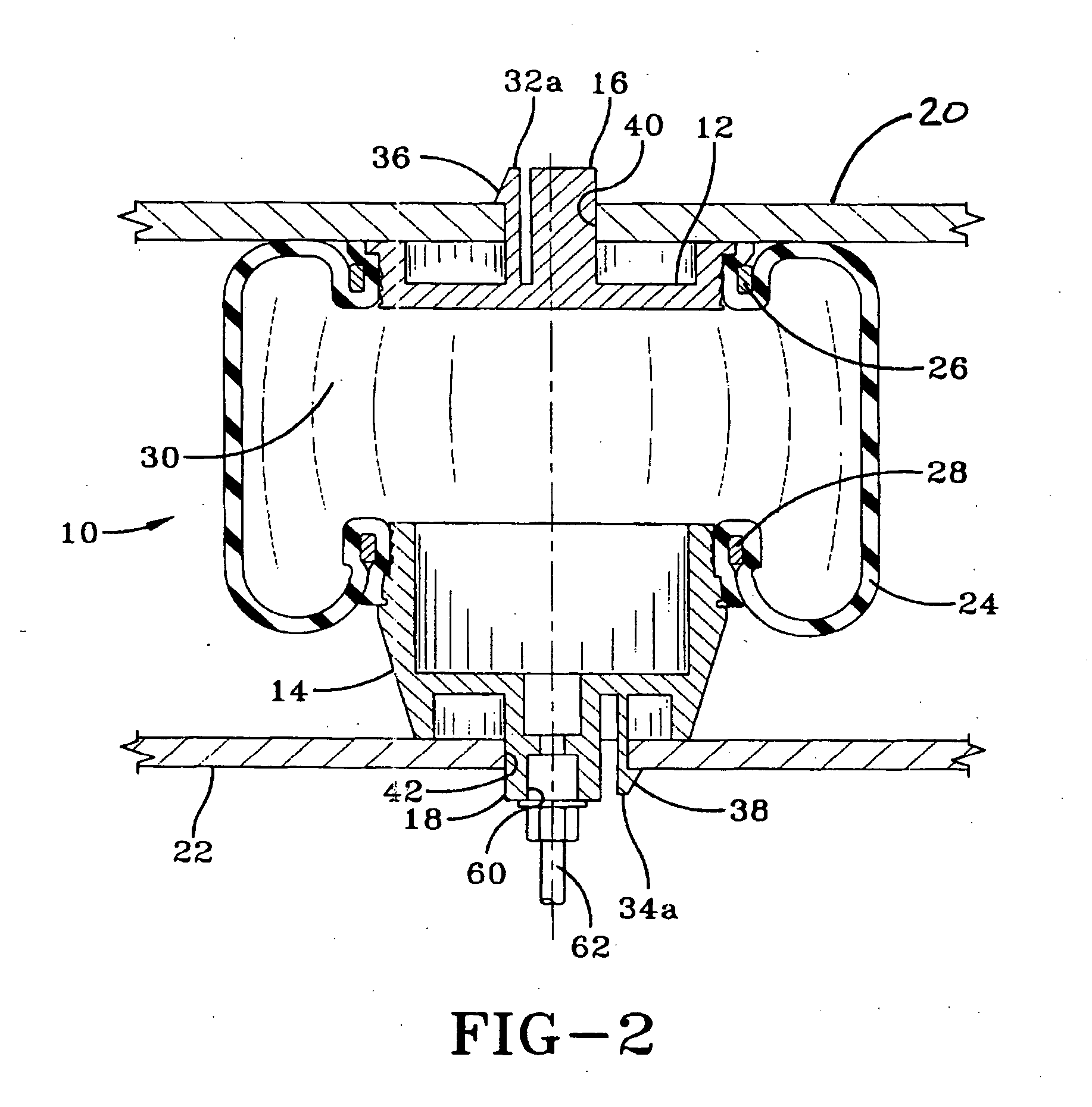
[0013] Referring now to FIGS. 1 and 2, there is shown an exemplary air spring mount 10, including upper and lower snap-in-place attachments that facilitate installation of the air spring mount 10 in an application. The air spring 10 includes upper and lower support plates 12, 14 having respective first and second mounting studs 16,18 for securing the air spring 10 to upper and lower mounting brackets 20, 22, respectively. A flexible elastomeric member 24, in the form of a cylindrical tube, is coupled at its respective ends to the upper and lower support plates 12, 14. Upper and lower rings 26, 28 are swaged to the support plates 12, 14 to crimp the ends of the elastomeric member 24 to the respective support plates 12, 14 to define a pressurizable chamber 30, as known in the art. While the elastomeric member 24 has been shown and described herein as having generally tubular configuration, with the ends of the tube swaged to respective support plates 12, 14 by swage rings 26, 28, it w...


PUM


Abstract

An air spring mount includes an elastomeric member coupled to at least one support plate to define a pressurizable chamber. The support plate has a snap-in-place attachment comprising a mounting stud projecting perpendicularly from the plate, and three resilient fingers spaced around the periphery of the stud. Barbs disposed in terminal ends of the fingers are biased outwardly by the fingers to engage a mounting bracket to which the air spring is mounted, when the attachment is inserted through a hole formed in the mounting bracket.

Description

FIELD OF THE INVENTION [0001] The present invention relates generally to suspension systems, and more particularly to an air spring mount used in a suspension system. BACKGROUND OF THE INVENTION [0002] Air spring mounts are commonly used in the suspension systems for Class 8 trucks to mount cabs and trailers to their respective chassis. Conventional air spring mounts include a flexible elastomeric member, typically in the form of a tube or sleeve, that is crimped, swaged or otherwise secured to a support plate such that the elastomeric member and support plate create a pressurizable chamber. The chamber can be filled with pressurized air, or alternatively, air can be selectively expelled from the chamber to adjust the height and stiffness of the mount relative to a desired supported load. This tunability of air spring mounts is particularly advantageous when the loads supported by the mounts vary significantly, such as the different loadings created, for example, by empty and fully ...

Claims


Application Information

Patent Timeline
IPC IPC(8): F16F9/04
CPCB60G11/28B60G2204/126B60G2204/44F16F9/05B60G2206/424B60G2206/82092F16F9/0454B60G2204/4404F16F9/54
Inventor ATTINELLO, JOHN S.BALL, DAVID W.TROWBRIDGE, MARK G.WOODLEE, JAMES E.
Owner VEYANCE TECH
Features
  • Generate Ideas
  • Intellectual Property
  • Life Sciences
  • Materials
  • Tech Scout
  • Unparalleled Data Quality
  • Higher Quality Content
  • 60% Fewer Hallucinations
Learn More