
Light source device

Inactive Publication Date: 2006-03-16
TOSHIBA MATSUSHITA DISPLAY TECH
View PDF6 Cites 24 Cited by
  • Summary
  • Abstract
  • Description
  • Claims
  • Application Information

AI Technical Summary

Benefits of technology

[0013] An object of this invention is to provide a light source device which can prevent flicker from becoming prominent in the dimmer control.
[0015] In the above light source device, since the duty ratios of the dimmer control signals are equal, the average luminance levels of the lamp-type light sources become the same. In addition, since the phases of the dimmer control signals are different, all of the lamp-type light sources can be prevented from being set into an ON state or OFF state, except a case wherein the brightness of the screen is set to 100% or 0%. That is, since brightness is changed for each display area by the dimmer control, flicker can be prevented from being prominent in comparison with a case wherein brightness is changed for the entire screen. Therefore, it becomes unnecessary to repeatedly turn ON and OFF the lamp-type light source at a high frequency. Further, since an area of the brightness change caused by the dimmer control is dispersed in the screen, it is possible to reduce the failure caused in the dimmer control when the screen of the display panel is formed of OCB liquid crystal pixels that require the black insertion driving.

Problems solved by technology

However, if the PWM dimmer signal of a relatively low frequency is used in a dimmer control for the brightness of the screen, flicker becomes prominent.
In this case, however, there occurs a problem that the lamp-type light source incompletely turns on when the ON time becomes extremely short.
Further, when the display panel is configured using OCB liquid crystal pixels that require the black insertion driving, it is difficult to control the brightness as desired since the brightness is influenced by a black insertion driving operation performed during the ON time of the lamp-type light source or an image display operation performed during the OFF time of the lamp-type light source.
Thus, failure in the dimmer control easily occurs.

Method used


Image

  • Light source device
  • Light source device
  • Light source device

Examples


Embodiment Construction

[0025] There will now be described a liquid crystal display device according to one embodiment of this invention with reference to the accompanying drawings.

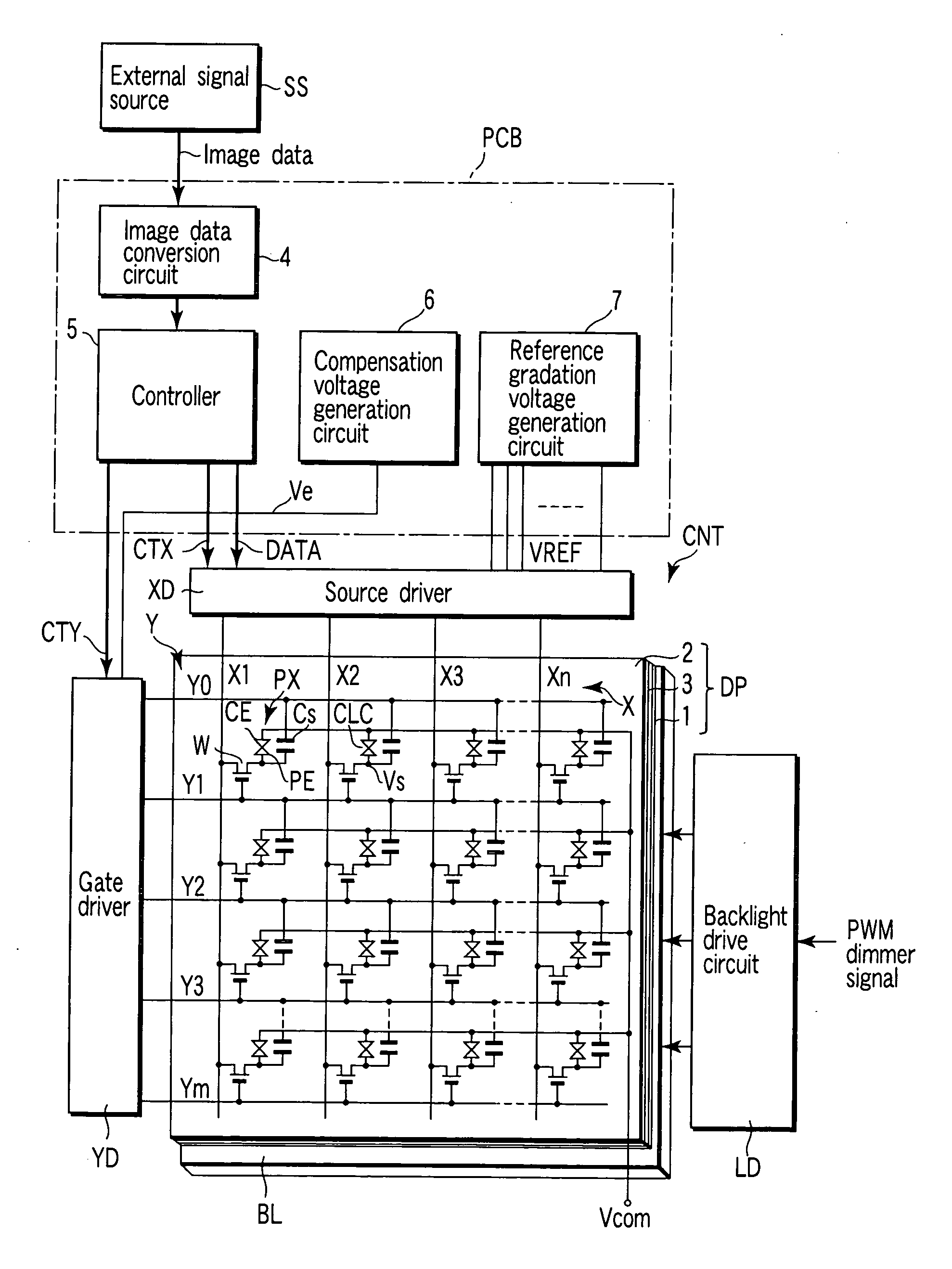
[0026]FIG. 1 schematically shows the circuit configuration of the liquid crystal display device. The liquid crystal display device includes a liquid crystal display panel DP, a display panel control circuit CNT connected to the display panel DP, a backlight BL which illuminates the display panel DP, and a backlight drive circuit LD which drives the backlight BL. The liquid crystal display panel DP has a structure in which a liquid crystal layer 3 is held between an array substrate 1 and a counter substrate 2 which are a pair of electrode substrates. For example, the liquid crystal layer 3 contains a liquid crystal material whose liquid crystal molecules are transferred in advance from a splay alignment to a bend alignment usable for a normally-white display, and are prevented from being inverse-transferred from the bend alignme...


PUM


Abstract

A light source device includes lamp-type light sources which respectively illuminate display areas obtained by dividing a screen of a display panel, and a backlight drive circuit which drives the lamp-type light sources. Particularly, the backlight drive circuit includes a dimmer control circuit which generates dimmer control signals having a common duty ratio which is changed to define ON time for each preset period of time and being set to different phases, and driving units which respectively drive the lamp-type light sources according to the dimmer control signals generated from the dimmer control circuit.

Description

CROSS-REFERENCE TO RELATED APPLICATIONS [0001] This application is based upon and claims the benefit of priority from prior Japanese Patent Application No. 2004-265640, filed Sep. 13, 2004, the entire contents of which are incorporated herein by reference. BACKGROUND OF THE INVENTION [0002] 1. Field of the Invention [0003] This invention relates to a light source device which is applied to a liquid crystal display panel of an OCB (Optically Compensated Birefringence) mode, for example. [0004] 2. Description of the Related Art [0005] A flat display device, represented by a liquid crystal display device, is widely used as a display device for a computer, car navigation system or television receiver. [0006] The liquid crystal display device generally has a liquid crystal display panel containing a matrix array of liquid crystal pixels and a display panel control circuit which controls the display panel. The liquid crystal display panel has a structure in which a liquid crystal layer is...

Claims


Application Information

Patent Timeline
IPC IPC(8): G09G3/36
CPCG09G3/3648G09G3/342G02F1/133
Inventor TERANISHI, KENTARO
Owner TOSHIBA MATSUSHITA DISPLAY TECH
Features
  • Generate Ideas
  • Intellectual Property
  • Life Sciences
  • Materials
  • Tech Scout
  • Unparalleled Data Quality
  • Higher Quality Content
  • 60% Fewer Hallucinations
Learn More