Provider network for providing L-2 VPN services and edge router

a provider network and edge router technology, applied in the direction of data switching networks, digital transmission, electrical devices, etc., can solve the problems of enormous management costs, provider cannot freely operate terminals, and parts of forwarding planes actually used by users cannot be checked

Inactive Publication Date: 2006-03-16
FUJITSU LTD
View PDF7 Cites 66 Cited by
  • Summary
  • Abstract
  • Description
  • Claims
  • Application Information

AI Technical Summary

Benefits of technology

[0039] According to the present invention, the edge router can check normality of traffic of a forwarding plane concerni...

Problems solved by technology

Thus, a part of the forwarding plane actually used by a user cannot be checked.
Consequently, the provider cannot freely operate the terminals.
Consequently, enormous management costs are necessary.
Additionally, in the case of the means (2), there is a problem in that it is difficult to install a testing device prepared by the provider for the user network therein.
Si...

Method used


Image

  • Provider network for providing L-2 VPN services and edge router
  • Provider network for providing L-2 VPN services and edge router
  • Provider network for providing L-2 VPN services and edge router

Examples


first embodiment

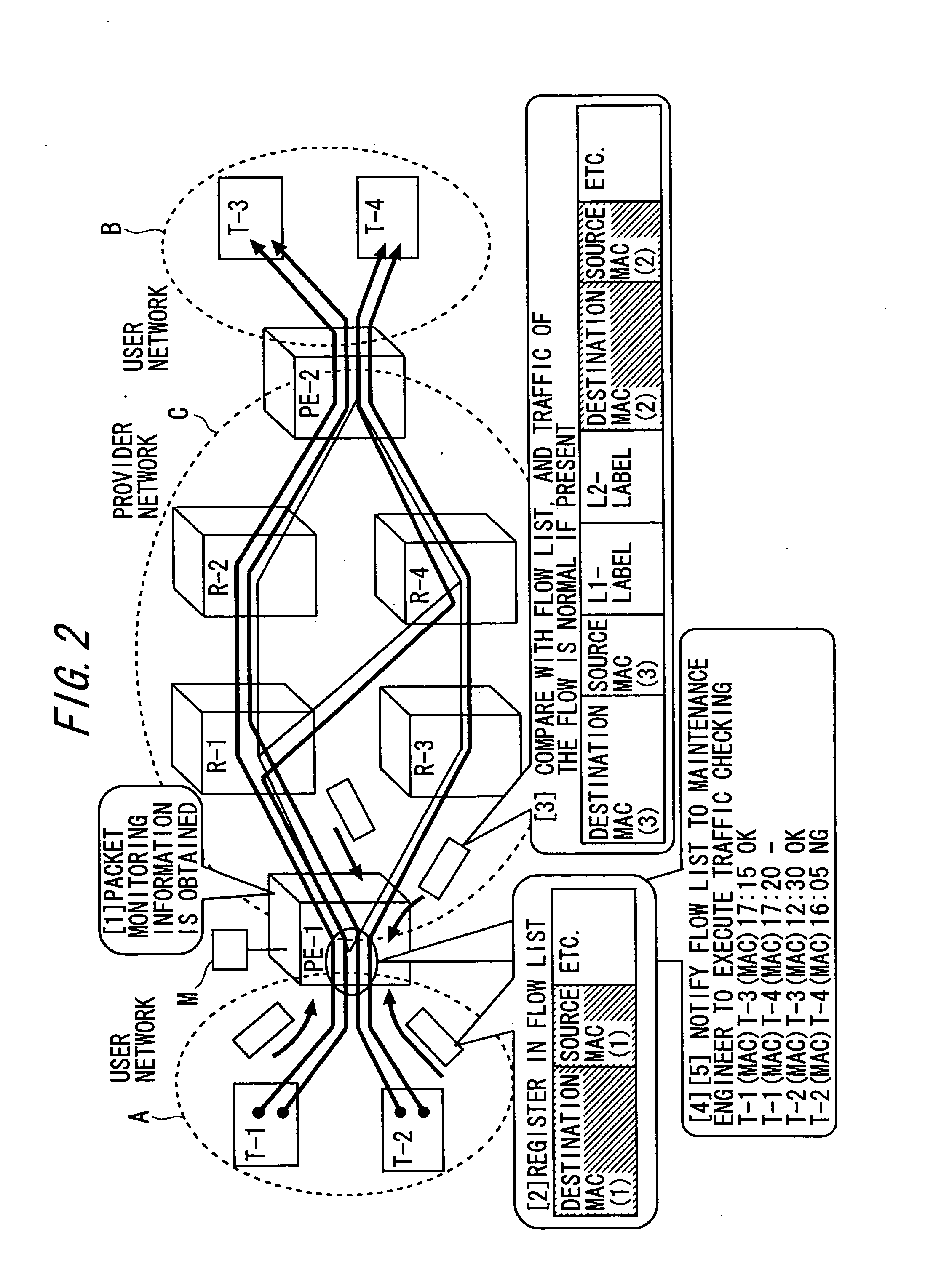
[0114]FIG. 2 is a diagram showing an entire configuration of an L2-VPN network system to which a first embodiment of the present invention is applied. FIG. 2 shows a network system in which a user network A and a user network B equivalent to customer sites are connected to a provider network C which renders L2-VPN services.

[0115] The provider network C is an MPLS network, and includes Provider edge routers (simply referred to as “edge routers” hereinafter) PE-1 and PE-2 arranged in boundaries between the user networks A and B and the provider network C, and core routers R-1, R-2, R-3 and R-4 arranged between the PE-1 and the PE-2.

[0116] The core routers R-1 and R-3 are connected to the edge router PE-1 through physical lines. The core routers R-2 and R-4 are connected to the edge router PE-2 through physical lines. The core router R1 is connected to the cores routers R-2 and R-4 through physical lines. The core router R3 is connected to the core router R-4 through a physical line....

modified example

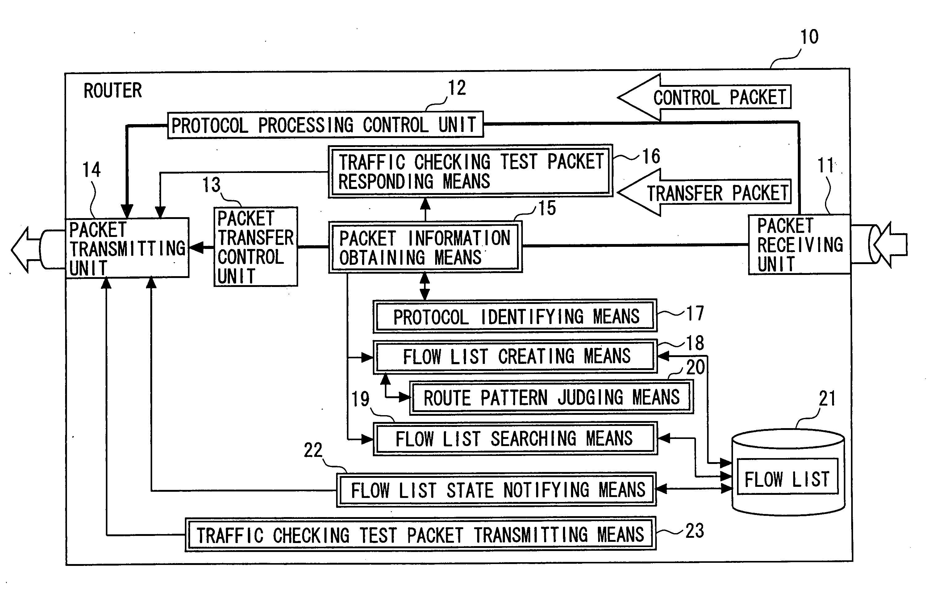
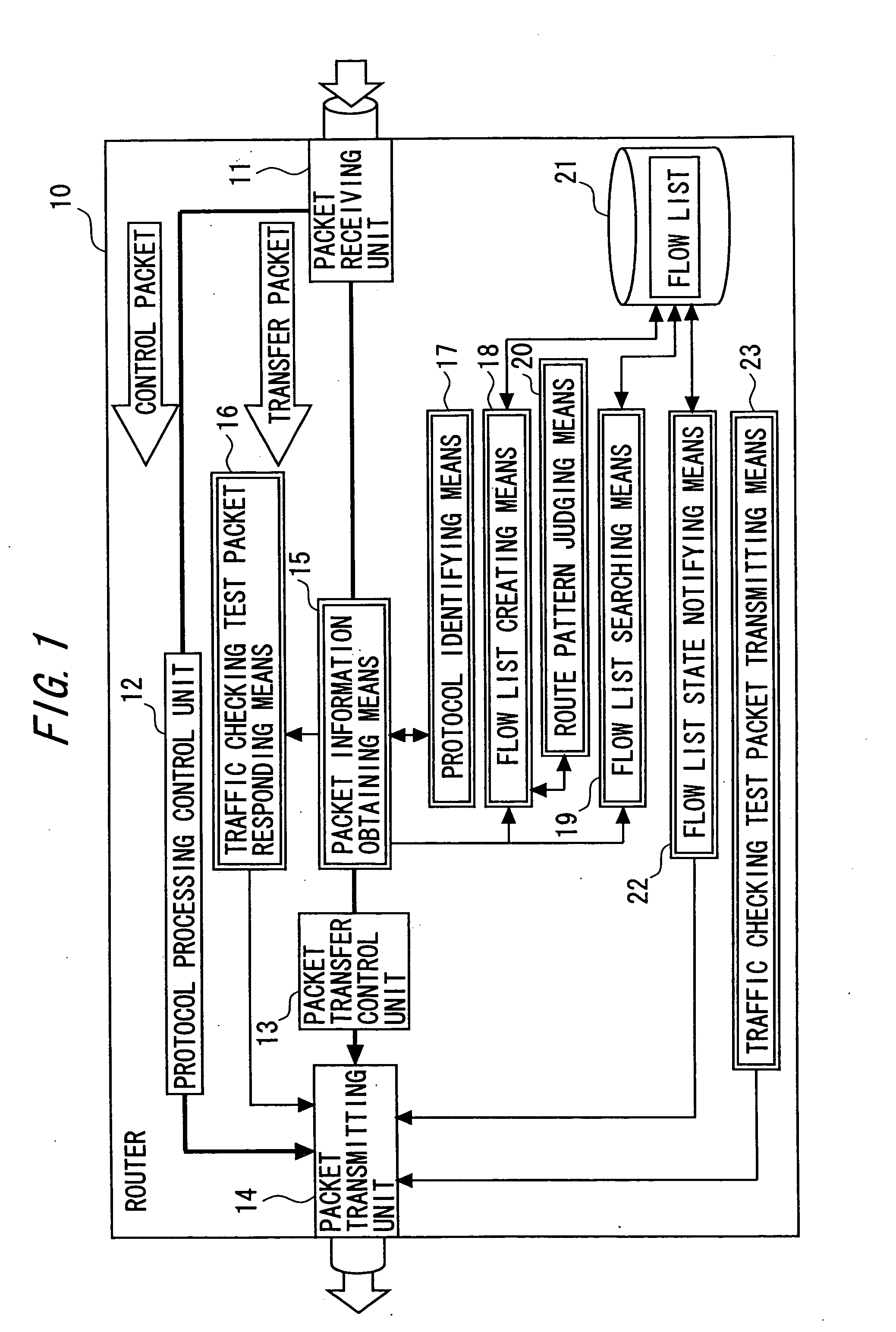
[0158] According to the first embodiment, when it discovers the entry of “TRAFFIC IS BEING CHECKED” in which a predetermined time has elapsed from the transmission time, the flow list state notifying unit 122 updates the state information of the entry to “ABNORMAL TRAFFIC”. In place of such a constitution, the following constitution can be employed. That is, when it discovers an entry in which MAC destination and source addresses (1) are similar in the flow list 121, the flow list creating unit 118 updates a transmission time of the entry if state information of the entry is either “TRAFFIC IS BEING CHECKED” or “NORMAL TRAFFIC”.

[0159] Then, the flow list state notifying unit 122 periodically monitors each entry, and searches for an entry in which a predetermined time has elapsed from the transmission time. At this time, when a relevant entry is discovered, state information of the entry is updated to be “ABNORMAL TRAFFIC”. Thus, searching is possible even in a case in which a traff...

second embodiment

[0160] Next, a second embodiment of the present invention will be described. The second embodiment includes components similar to those of the first embodiment, and thus description thereof will be omitted. Different components will be described.

[0161]FIG. 7 is a diagram showing an entire configuration of a network system according to the second embodiment. FIG. 8 is a diagram showing a constitutional example of a router 210 applied to the second embodiment. In FIG. 7, the configuration of the network system is similar to that of the first embodiment.

[0162] The router 210 shown in FIG. 8 includes a packet information obtaining unit 215, a flow list creating unit 218, a flow list searching unit 219, a route pattern judging unit 220, a flow list state notifying unit 222, and a storage unit 21 corresponding to the packet information obtaining means 15, the flow list creating means 18, the flow list searching means 19, the route pattern judging means 20, the flow list state notifying ...


PUM


Abstract

The provider network that interconnects user networks includes a plurality of edge routers. At least one of the plurality of edge routers includes an obtaining unit for obtaining information of a packet transferred by the edge router itself, a creating unit for creating a flow list in which flow information of packets transferred from the user network side to the provider network side is registered based on the packet information, a monitoring unit for monitoring a traffic state of a flow of each packet registered in the flow list based on information of packets transferred from the provider network to the user network, and a notifying unit for notifying the traffic state of the flow registered in the flow list to a maintenance engineer.

Description

BACKGROUND OF THE INVENTION [0001] 1. Field of the Invention [0002] The present invention relates to a traffic checking / state monitoring system of a forwarding plane (packet transfer function through full wire not by software but by packet transfer only hardware) of a router which constitutes a Layer 2-Virtual Private Network (L2-VPN). [0003] 2. Description of the Related Art [0004] In recent years, at corporations or the like whose bases are dispersed to several places, a form has increasingly been taken to interconnect the bases of the places through an Internet network, and to virtually build one local area network (L2-VPN). This has been accompanied by a rapid increase in the number of providers for rendering L2-VPN connection services. [0005] The L2-VPN is a VPN through which the provider offers a layer 2 connection between customer sites. In the L2-VPN, a provider network which renders VPN services interconnects user networks equivalent to the customer sites. [0006] A provider...

Claims


Application Information

Patent Timeline
IPC IPC(8): H04L12/28H04L45/50
CPCH04L45/50H04L43/026
Inventor ISHII, KENICHITAKAKI, HIROKIPETERS, COLINKURANARI, SHINICHI
Owner FUJITSU LTD
Why Eureka
Try Eureka