Access router and terminal device
a terminal device and router technology, applied in the direction of electrical equipment, data switching networks, digital transmission, etc., can solve the problems of ipv6 network not being able to ensure the communication quality to users' satisfaction, no established technique for managing a host and another host, and deteriorating quality, so as to reduce the number of hosts belonging to the second network
- Summary
- Abstract
- Description
- Claims
- Application Information
AI Technical Summary
Benefits of technology
Problems solved by technology
Method used
Image

Examples
first embodiment
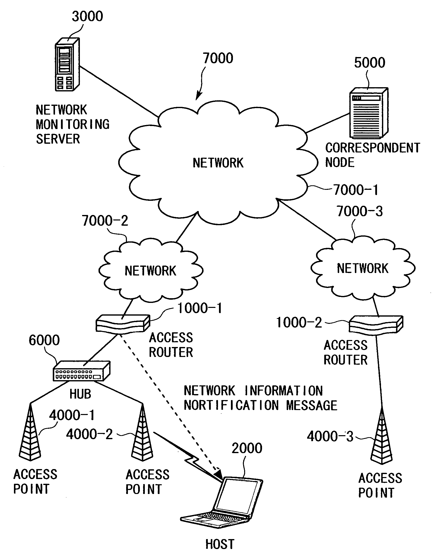
[0240] A first embodiment is an embodiment of an access router according to the present invention. The first embodiment is described with reference to the system configuration shown in FIG. 1, the access router 1000 shown in FIG. 3, the processing sequences shown in FIGS. 10, 12, 14, 15, and 17, the network information notification format shown in FIGS. 27 to 31, and the tables shown in FIGS. 4 to 9.
[0241] A network system in the first embodiment has a configuration as the one shown in FIG. 1. At least, the access router 1000 is employed as the access router 1000-1 shown in FIG. 1. The access router 1000 has the tables shown in FIGS. 4 to 9.
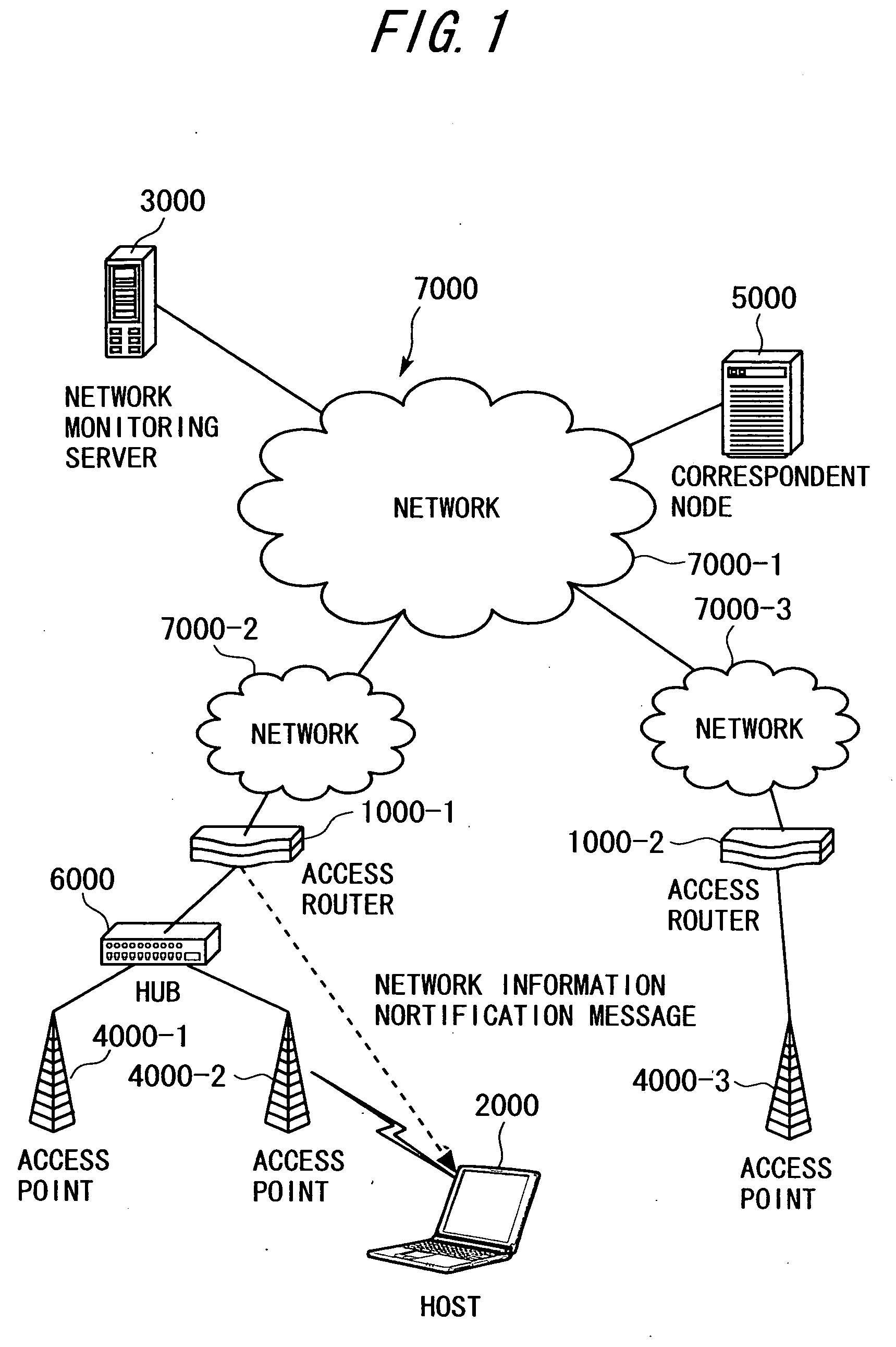
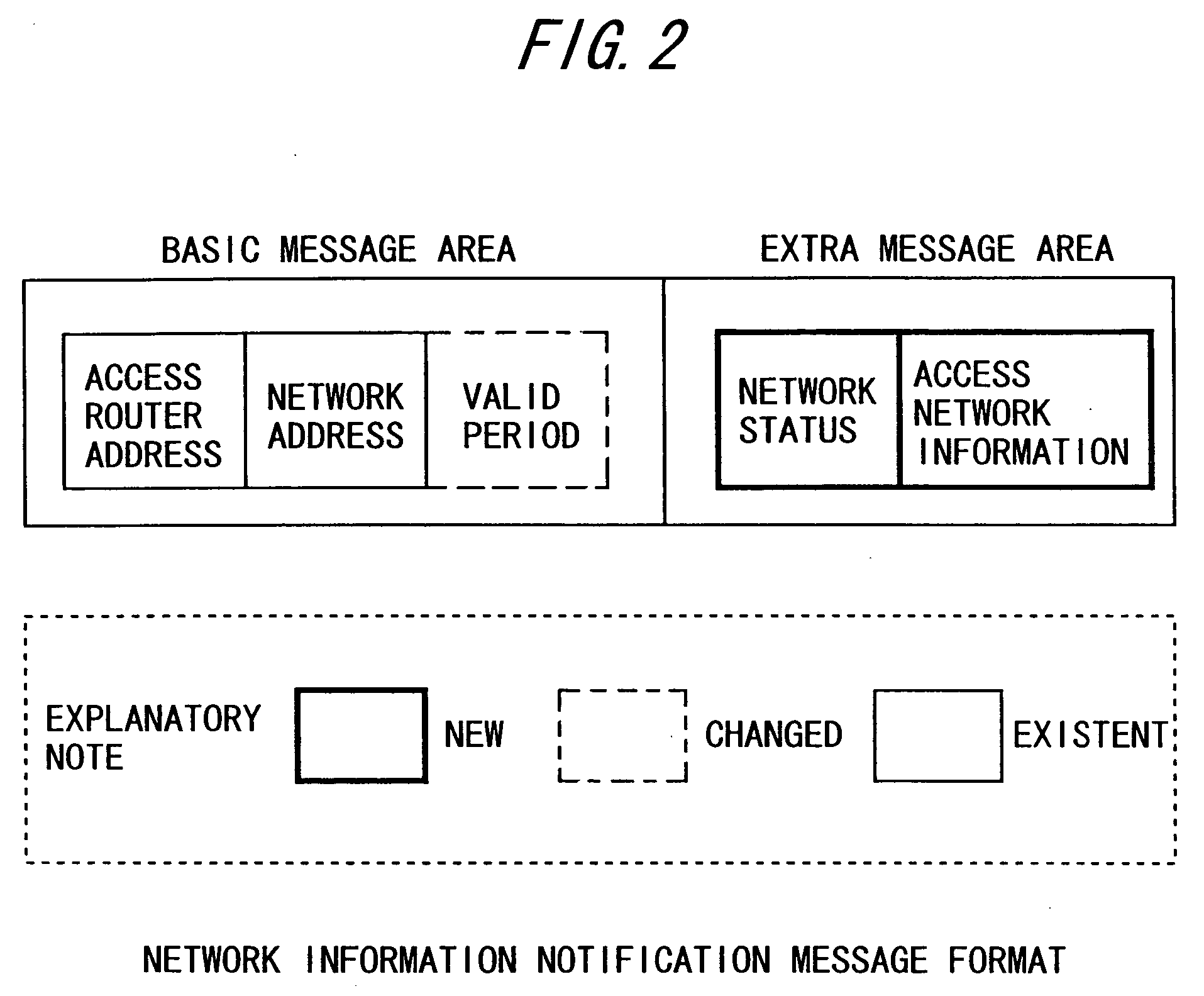
[0242] Employed in the first embodiment as RA to be sent from the access router 1000-1 to the host 2000 is RA that contains extra message areas (option fields) where the network status and access network information as those shown in FIGS. 27 to 31 are set.
[0243] Described in the first embodiment are (1) the operation of the access router 1000...
second embodiment
[0297] A second embodiment is an embodiment of a host according to the present invention. The second embodiment is described with reference to the network configuration shown in FIG. 1, the configuration of the host 2000 shown in FIG. 19, and the processing sequences shown in FIGS. 20, 21, 23, and 25.
[0298] Described in the second embodiment are (1) the operation of the host 2000 according to the present invention to switch to a data link leading to the access point 4000-3 when an RA message is not received in response to an RS message the host 2000 has sent via the access point 4000-1 to which the host 2000 has been connected (first switching operation, which corresponds to the processing 2-1 in the embodiment mode), and (2) the operation of switching to a data link leading to the access point 4000-3 as a result of network status analysis upon reception of an RA message (second switching operation, which corresponds to the processing 2-2 in the embodiment mode).
[0299]>
[0300] The ...
third embodiment
[0318] A third embodiment is an embodiment of a network system that includes an access router and host according to the present invention. The third embodiment is described with reference to the system configuration diagram shown in FIG. 1, the access router 1000 shown in FIG. 3, the host 2000 shown in FIG. 19, and the processing sequences of FIGS. 17, 23, and 25.
[0319] As shown in FIG. 1, the host 2000 belongs to the access point 4000-2 and is connected to the access router 1000-1 via the hub 6000. Described in the third embodiment is the operation of switching data links in order to switch to the network 7000-3 to which the access router 1000-2 belongs by reconnecting the host 2000 to the access point 4000-3 upon reception of an RA message from the access router 1000-1 after the network 7000-1 falls into a congestion state.
[0320] In the processing sequence of FIG. 17, the transmission interval controlling unit 1060 in the access router 1000-1 requests, when the network informati...
PUM
 Abstract
Description
Claims
Application Information
 - R&D
- Intellectual Property
- Life Sciences
- Materials
- Tech Scout
- Unparalleled Data Quality
- Higher Quality Content
- 60% Fewer Hallucinations
Browse by: Latest US Patents, China's latest patents, Technical Efficacy Thesaurus, Application Domain, Technology Topic, Popular Technical Reports.
© 2025 PatSnap. All rights reserved.Legal|Privacy policy|Modern Slavery Act Transparency Statement|Sitemap|About US| Contact US: help@patsnap.com