Piezoelectric actuator and pump using same

a technology of ferroelectric actuators and miniature diaphragm pumps, which is applied in the direction of positive displacement liquid engines, pumping machines, machines/engines, etc., can solve the problems of inapposite prior art and no prior art showing a flex valve with a miniature pump

Inactive Publication Date: 2006-03-16
ADAPTIVENERGY
View PDF45 Cites 23 Cited by
  • Summary
  • Abstract
  • Description
  • Claims
  • Application Information

AI Technical Summary

Benefits of technology

[0010] This invention is a method for making a high-displacement ferroelectric actuator, in this case a piezoelectric actuator. This piezoelectric actuator may then be used as the diaphragm in a small diaphragm pump. The pump is small, lightweight, quiet, and efficient. The best mode, a round pump about 40 mm[1.5″] in] diameter by about 13 mm[0.5″]thick and weighing approximately 35 g [one ounce], can

Problems solved by technology

Such pumps generally pump only a drop of fluid at a time; because of the small forces and low Reynolds numbers in

Method used


Image

  • Piezoelectric actuator and pump using same
  • Piezoelectric actuator and pump using same
  • Piezoelectric actuator and pump using same

Examples


Embodiment Construction

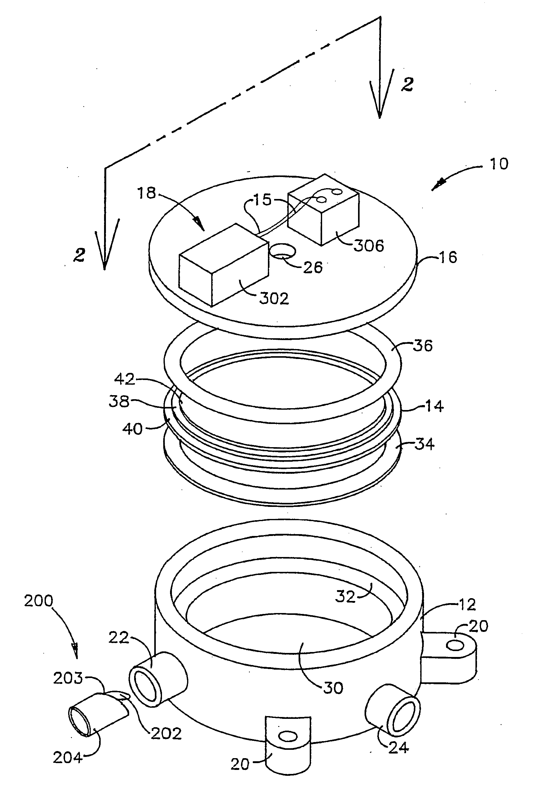
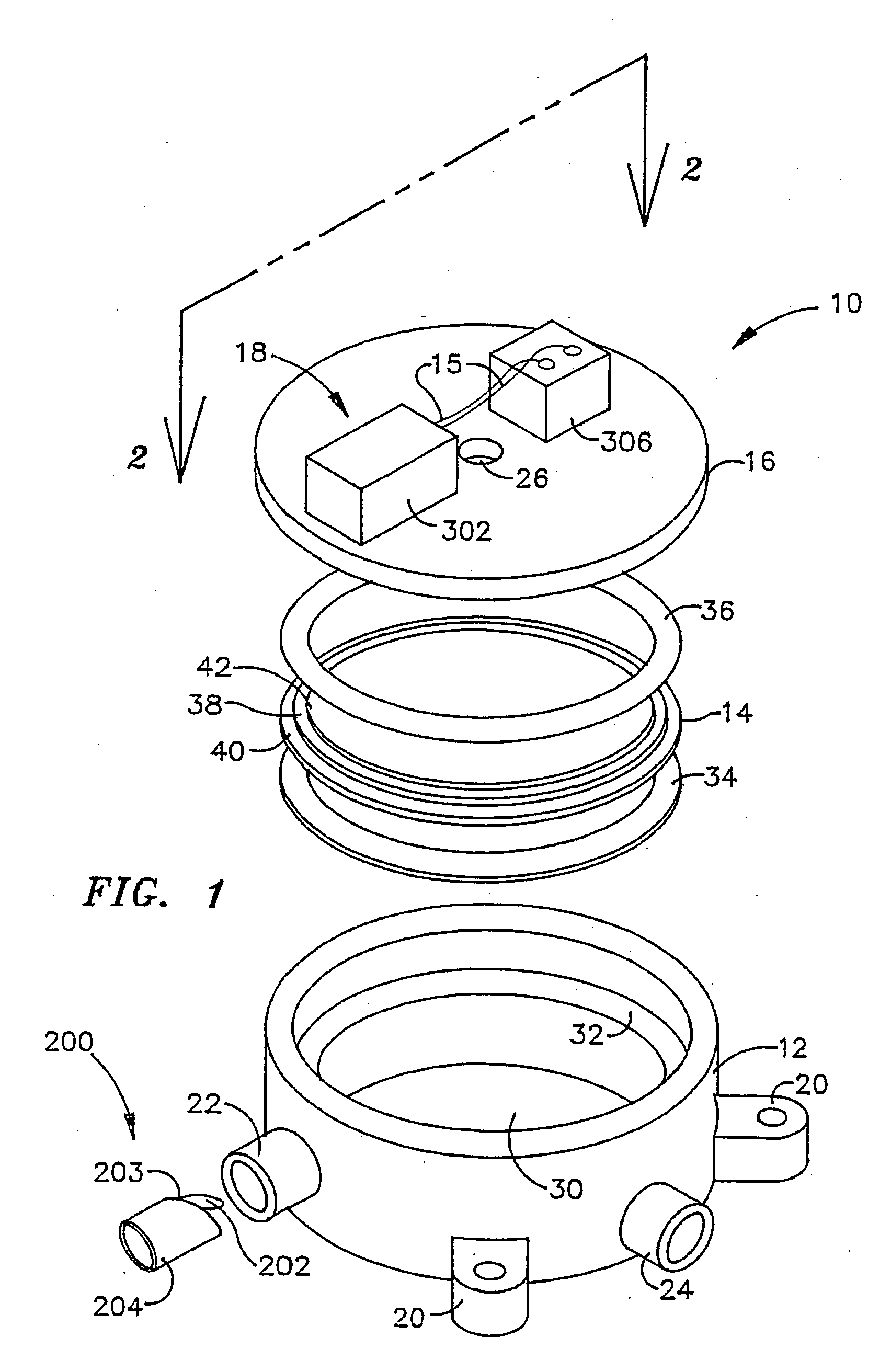
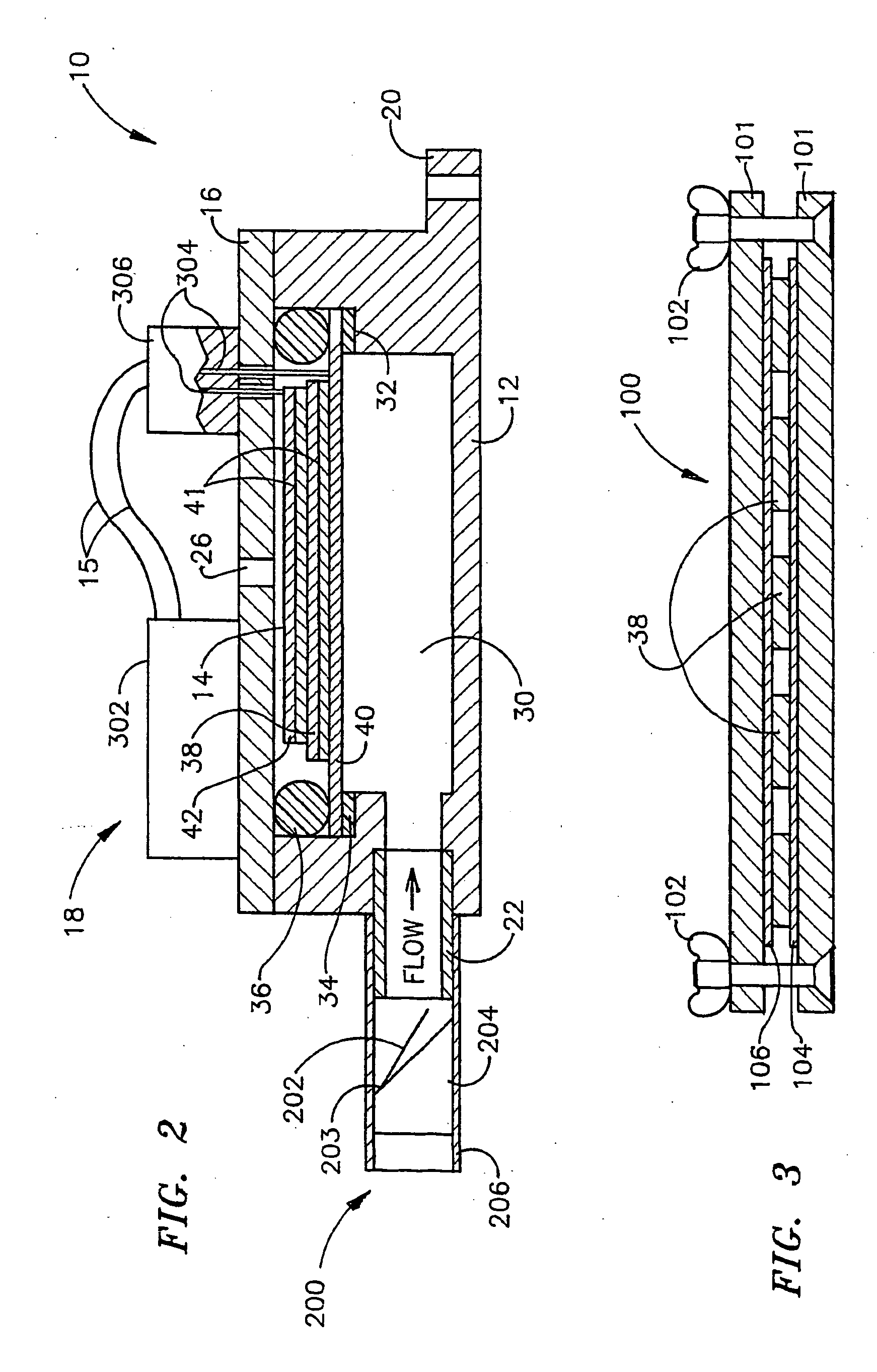
[0017]FIG. 1 shows how the piezoelectric actuator of the present invention may be used in a miniature diaphragm pump. The pump 10 is generally in the form of a circular short cylinder. It includes the pump body 12, piezoelectric actuator 14, pump cover 16 and piezoelectric actuator electronic driver circuit 18. The pump body 12 has lugs 20 for mounting the pump to any substrate. Inlet 22 and outlet 24 are part of the pump body 12 though they could be separate pieces otherwise fastened to the pump body. The pump cover 16 is essentially the same diameter and of the same material as the pump body 12. The material would ordinarily be of a standard plastic such as acetal[DELRIN®], PVC, or PC, or of a metal such as stainless steel or brass. These are preferable since they can be easily machined or thermally formed. The cover 16 may be fastened to the pump body 12 by any means such as by a fast-curing adhesive while the pump body 12 and cover 16 are under compression such as by clamping. T...


PUM

PropertyMeasurementUnit
Thicknessaaaaaaaaaa
Forceaaaaaaaaaa
Diameteraaaaaaaaaa

Abstract

A method of manufacturing piezoelectric actuators (14) is disclosed along with a miniature diaphragm pump (10) using the actuators. The object was an actuator which could be used in miniature diaphragm pumps and other applications and which would be smaller in size and simpler to manufacture than prior art actuators, yet would provide forces and displacements an order of magnitude higher than any previously known devices of similar size. The pump (10) incorporates the new actuator along with a novel one-way valve (200) and a small driver circuit (18). The pump is of direct application in the liquid cooling systems of small computers, and in other fluid systems.

Description

[0001] This application claims the benefit of U.S. Provisional Patent Application No. 60 / 233248 filed 18 Sep. 2000[18 / 09 / 00].TECHNICAL FIELD [0002] The present invention is in the field of the manufacture of ferroelectric actuators and miniature diaphragm pumps using these actuators as the prime mover. In the best mode the actuators are piezoelectric. BACKGROUND ART [0003] The prior art for this invention may be grouped as follows: [0004] I. U.S. Pat. Nos. 5,471,721, 5,632,841, 5,849,125, 6,162,313, 6,042,345, 6,060,811, and 6,071,087 showing either prestressing of piezoelectric actuators, or dome-shaped piezoelectric actuators, or both. This prior art is generally inapposite because the present invention does not use a prestressed or dome-shaped piezoelectric actuator. [0005] II. U.S. Pat. Nos. 6,179,584, 6,213,735, 5,271,724, 5,759,015, 5,876,187, 6,227,809 showing so-called micropumps. Such pumps generally pump only a drop of fluid at a time; because of the small forces and low R...

Claims


Application Information

Patent Timeline
IPC IPC(8): F04B17/03H01L41/053F04B9/00F04B43/04H01L41/047H01L41/09H01L41/24
CPCF04B43/04F04B43/046H01L41/047Y10T29/42H01L41/313Y10T29/49128H01L41/0973H10N30/802H10N30/877H10N30/2047H10N30/06H10N30/00H10N30/87
Inventor EAST, W. JOE
Owner ADAPTIVENERGY
Why Eureka
Try Eureka