Method for curing a binder on insulation fibers

a technology of fibrous insulation and curing method, which is applied in the direction of thin material processing, transportation and packaging, textiles and papermaking, etc., can solve the problems of short-cut air flow path becoming hot spots, and achieve the effect of slow curing rate of the binder

Inactive Publication Date: 2006-03-16
CERTAINTEED CORP
View PDF72 Cites 15 Cited by
  • Summary
  • Abstract
  • Description
  • Claims
  • Application Information

AI Technical Summary

Benefits of technology

[0007] The invention relates to a method of curing a binder on insulation fibers of a fibrous insulation by, adjusting a temperature of a heated gas to a binder curing temperature, and directing the heated gas to flow in an adjusted ratio of, downwardly into the fibrous insulation and upwardly into the fibrous insulation, to cure the binder and to compensate for a slow curing rate of the binder on corresponding insulation fibers within an interior of the fibrous insulation.

Problems solved by technology

However, a known accumulation process of making a fibrous insulation assembles the insulation fibers according to an uneven distribution, creating short-cut air flow paths among corresponding insulation fibers in the fibrous insulation.
When heated gas is directed into the fibrous insulation to cure the binder, the short-cut air flow paths become hot spots.

Method used


Image

  • Method for curing a binder on insulation fibers
  • Method for curing a binder on insulation fibers
  • Method for curing a binder on insulation fibers

Examples


Embodiment Construction

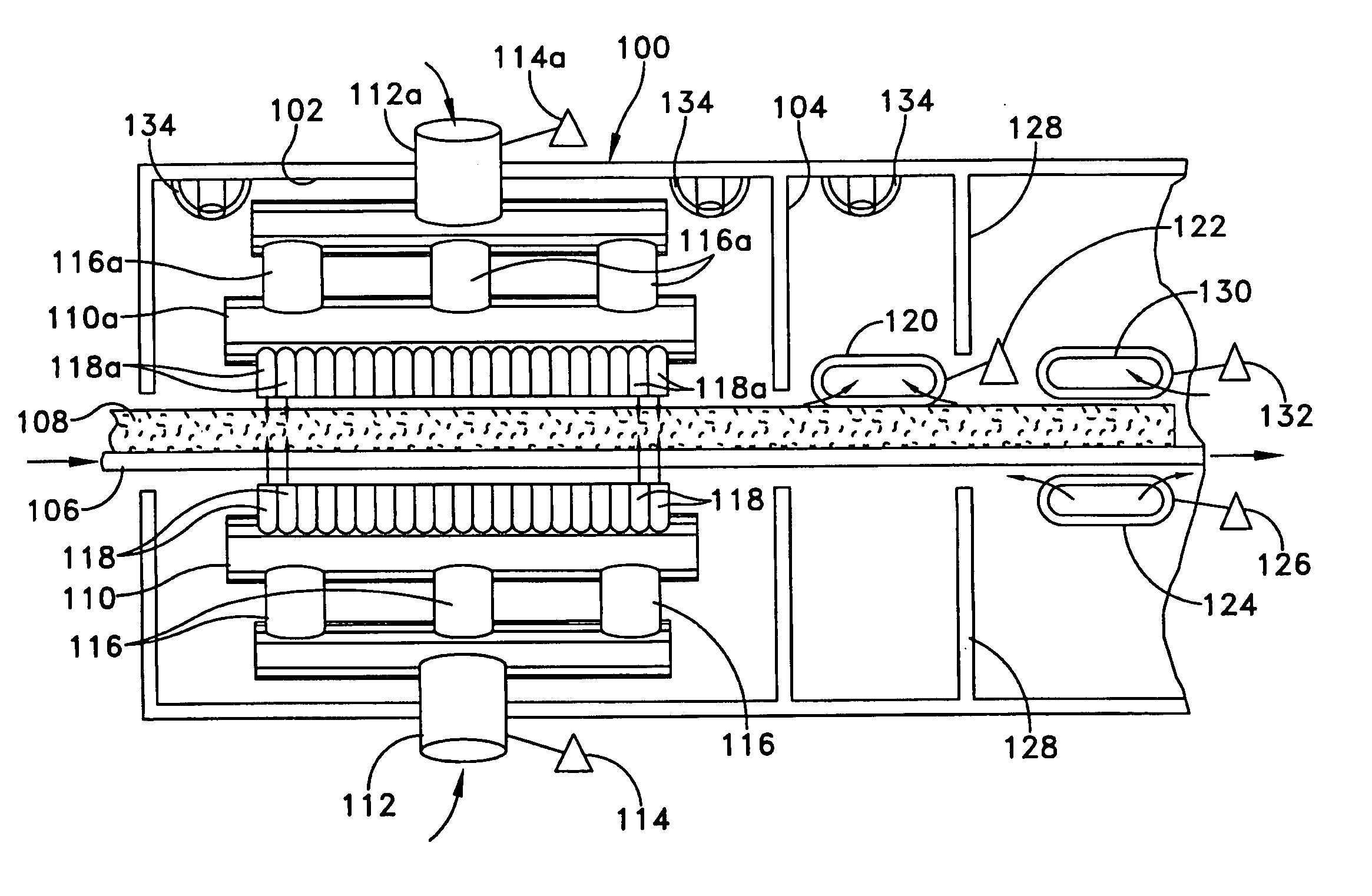
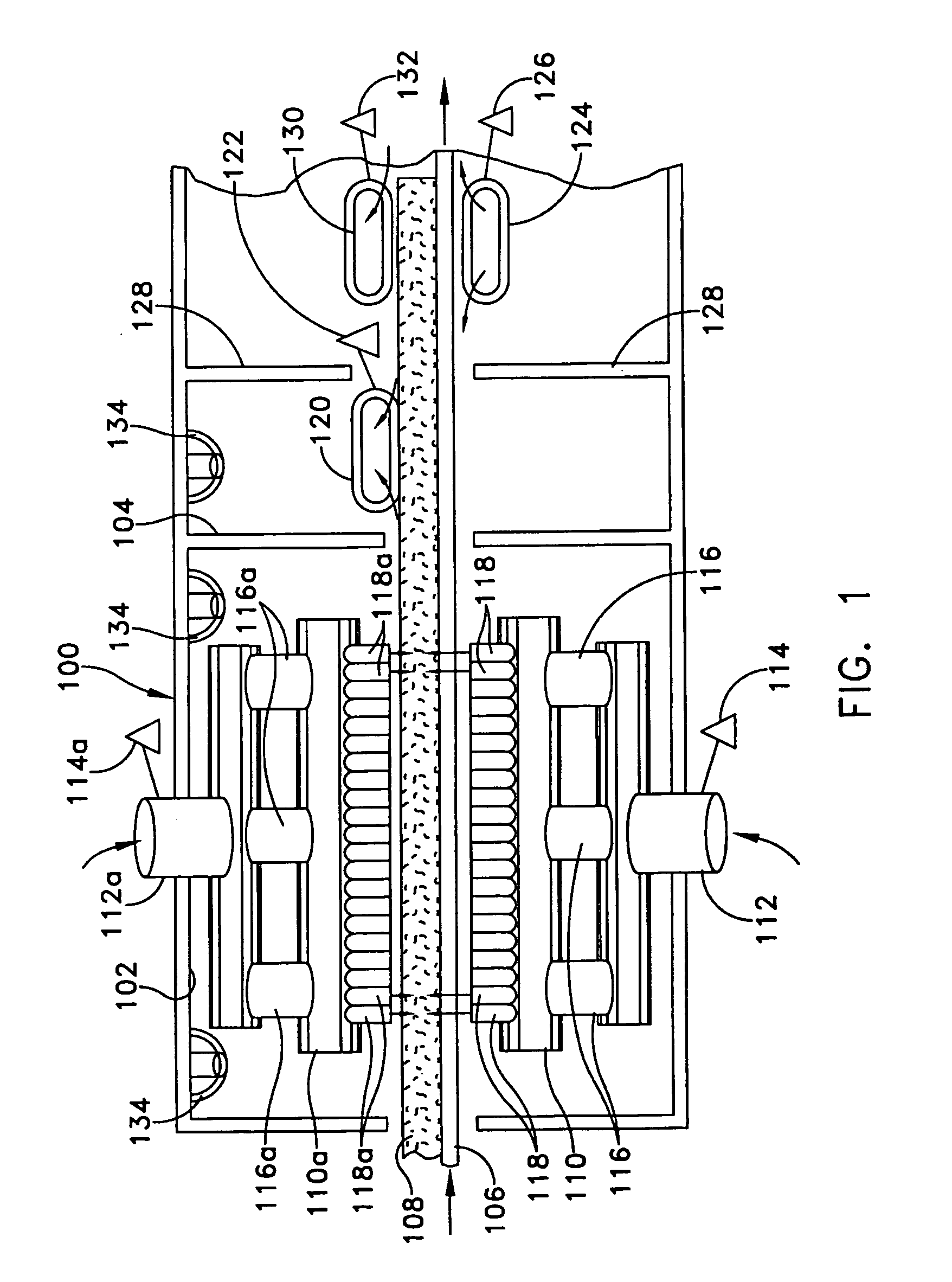
[0017]FIG. 1 discloses a curing oven (100) having a heavily insulated heating zone chamber (102), and an adjacent, insulated cooling zone chamber (104). A combination of a heating zone chamber (102) and a cooling zone chamber (104) forms a single stage of the curing oven (100). A continuous moving conveyor (106) supports a fibrous insulation (108) formed by a mass of numerous insulation fibers that are assembled on the conveyor (106). A binder is dispersed among the insulation fibers, and the insulation fibers are assembled on the conveyor (106) to form a lofted fibrous insulation (108).

[0018]FIG. 3 discloses another embodiment of the fibrous insulation (108). A continuous web of glass fiber non-woven facing layer (300) may be dispensed from a roll (302) and is applied to at least one of the two major sides of the fibrous insulation (108) before the fibrous insulation (108) enters the curing oven (100). The facing layer (300) is a flexible sheet or film that is attached to, and cov...


PUM

PropertyMeasurementUnit
densityaaaaaaaaaa
densityaaaaaaaaaa
thicknessaaaaaaaaaa

Abstract

The invention relates to curing a binder on fibrous insulation (108), wherein, heated gas flows as a ratio of, an upward flow into the fibrous insulation (108), and a downward flow into the fibrous insulation (108), to heat the binder to its curing temperature; and the binder is cooled, thereby curing at least a portion of the binder to a thermoset state. When a remainder of the binder remains uncured, another stage of heating the binder with a ratio of heated gas followed by cooling, will cure the remainder of the binder.

Description

CROSS-REFERENCES TO RELATED APPLICATIONS [0001] This application is related to U.S. patent application Ser. No. 10 / 851,535, filed May 21, 2004 (attorney docket D0932-00463). U.S. patent application Ser. No. 10 / 851,535, filed May 21, 2004 is a continuation in part of U.S. patent application Ser. No. 10 / 781,994, filed Feb. 19, 2004, which is a continuation-in-part of the following copending United States patent applications: U.S. patent application Ser. No. 10 / 689,858, filed Oct. 22, 2003; U.S. patent application Ser. No. 09 / 946,476, filed on Sep. 6, 2001; and U.S. patent application Ser. No. 10 / 766,052, filed on Jan. 28, 2004; which are commonly assigned and hereby incorporated by reference. [0002] This application is also related to U.S. Pat. No. 6,673,280, issued Jan. 6, 2004, and U.S. patent application Ser. No. 10 / 766,052, filed on Jan. 28, 2004, U.S. patent application Ser. No. 10 / 782,275, filed on Feb. 19, 2004, U.S. patent application Ser. No. 10 / 781,994, filed on Feb. 19, 200...

Claims


Application Information

Patent Timeline
Patent Type & Authority Applications(United States)
IPC IPC(8): B29C71/00B29C71/02B29B17/00
CPCB29C35/06D04H13/007D04H13/006B29C67/245D04H1/4209D04H1/64D04H1/655Y10T428/249924
Inventor YANG, ALAINBOUQUET, FRANCOISTRABOLD, MARK
Owner CERTAINTEED CORP
Why Eureka
Try Eureka