Mobile communication terminal

Inactive Publication Date: 2006-03-16
MITSUBISHI ELECTRIC CORP
View PDF5 Cites 48 Cited by
  • Summary
  • Abstract
  • Description
  • Claims
  • Application Information

AI Technical Summary

Benefits of technology

[0006] Therefore, the mobile communication terminal in accordance with the present invention can prevent itself from being fraudulently used when a user has got the mobile communication terminal illegally and then attaches an IC card which he or she has got legally to the mobile communication terminal.

Problems solved by technology

A problem with this method is however that when a user attaches an IC card which he or she has got legally to the mobile communication terminal which he or she has got illegally, he or she can use the mobile communication terminal itself with no holds barred.

Method used


Image

  • Mobile communication terminal
  • Mobile communication terminal
  • Mobile communication terminal

Examples


embodiment 1

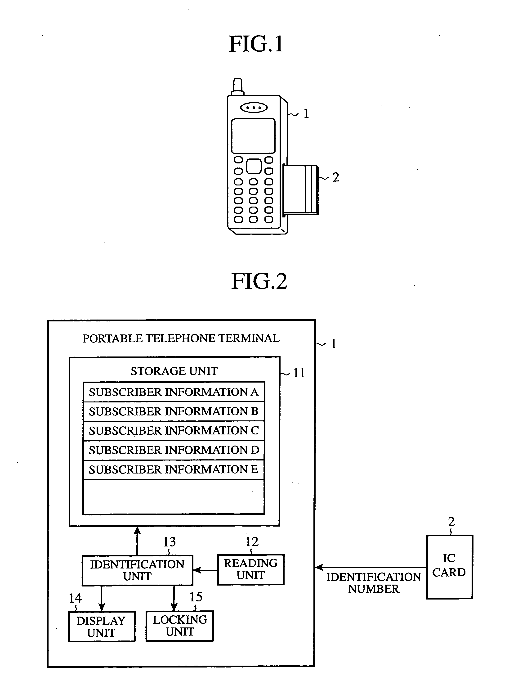
[0016]FIG. 1 is a diagram showing a portable telephone terminal in accordance with this embodiment 1. The portable telephone terminal (i.e., a mobile communication terminal) 1 is provided with a slot (not shown) disposed on a side or back surface thereof, to and from which an IC card 2 can be attached and detached. When the IC card 2 is inserted into this slot, the portable telephone terminal is electrically connected with the IC card 2. A subscriber's (or an owner's) identification number is stored in the IC card 2. When this IC card 2 is inserted into the portable telephone terminal 1, the portable telephone terminal 1 can be made to communicate with a base station so that the user can talk over the telephone.

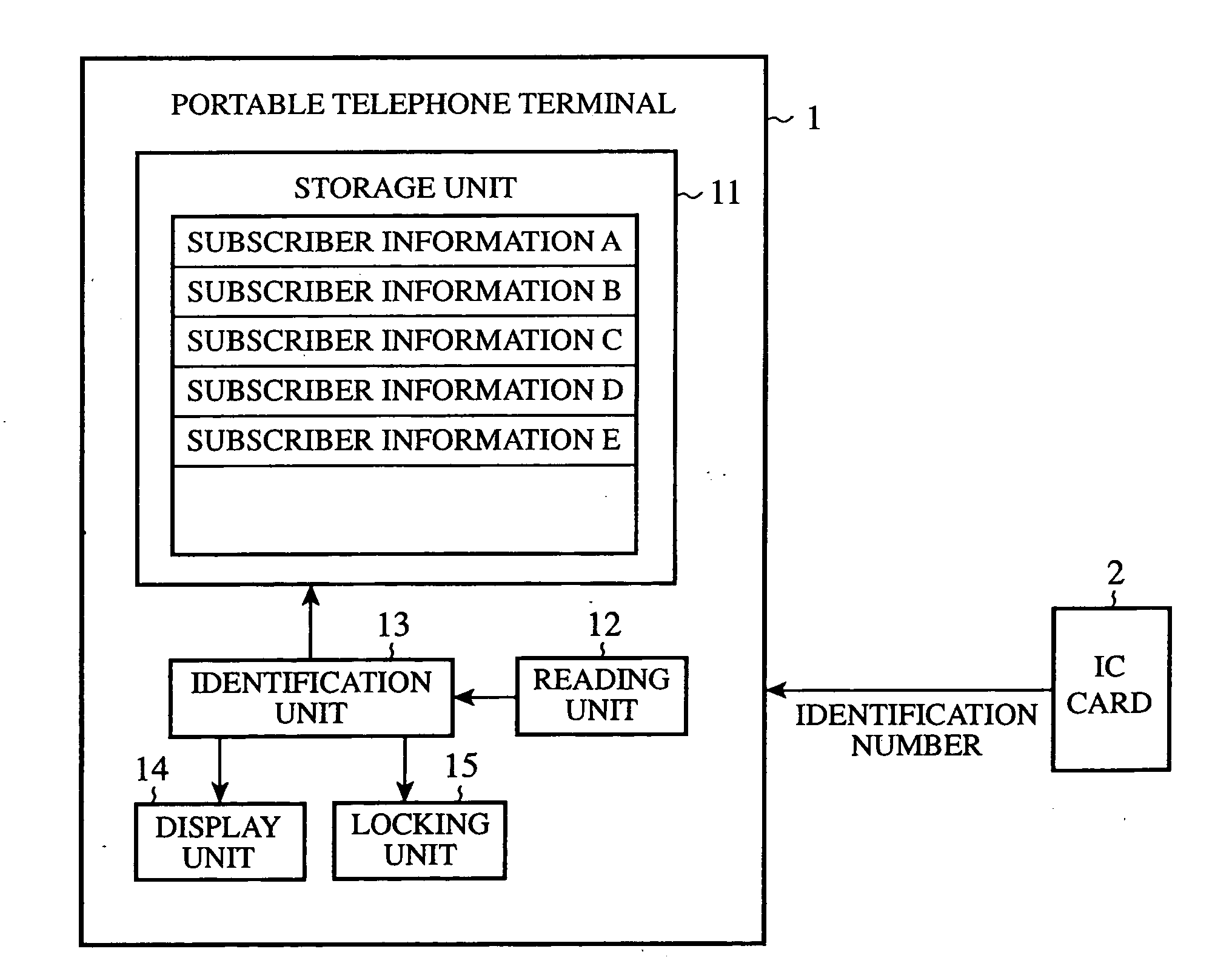
[0017]FIG. 2 is a block diagram of the portable telephone terminal 1. As shown in this figure, the portable telephone terminal 1 is provided with a storage unit 11, a reading unit 12, an identification part (i.e., an identification processing unit) 13, a display unit (i.e., ...

embodiment 2

[0026]FIG. 4 is a diagram showing communications between a portable telephone terminal in accordance with this embodiment 2 and a base station. The portable telephone terminal 1 shown in the figure can carry out communications when an IC card 2 is inserted thereinto, like that of embodiment 1. A subscriber's (i.e., an owner's) identification number is stored in the IC card 2. Usually, when the terminal or the IC card has been stolen, the subscriber makes contact with a business firm with which he or she makes a contract for the subscription. On this occasion, the business firm registers both the ID of the theft terminal and the identification number and subscriber information of the theft IC card, as theft information about the subscriber, in response to the contact from the subscriber. The terminal can acquire information about the theft terminal or the theft IC card which is retrieved based on the above-mentioned theft information via a base station.

[0027]FIG. 5 is a block diagra...

embodiment 3

[0036]FIG. 7A is a diagram showing information stored in a related art portable telephone terminal, and FIG. 7B is a diagram showing information stored in a portable telephone terminal in accordance with embodiment 3 of the present invention. Since data in the form as shown in FIG. 7A are stored in a related art portable telephone terminal, when an authorized IC card is inserted into the portable telephone terminal, all information stored in the terminal can be read by the IC card. In contrast, according to this embodiment 3, telephone book data, stored e-mails, a record of incoming calls, etc., are stored for each of a plurality of available IC cards, as well as the identification number of each of the plurality of IC cards, as shown in FIG. 7B. Therefore, the portable telephone terminal in accordance with this embodiment can restrict data which can be read for every IC card inserted thereto.

[0037] The portable telephone terminal in accordance with this embodiment 3 has the same s...


PUM


Abstract

When an IC card is inserted into a mobile communication terminal, a reading unit reads the identification number of the IC card from the IC card and then notifies it to an identification unit, and the identification unit determines whether or not the acquired information is stored in a storage unit. When the identification number of the inserted IC card is not stored in the storage unit, the identification unit makes a request of a display unit to display a request to input a password peculiar to the portable telephone terminal. The identification unit then recognizes a password input by a user, and, when determining that the input password differs from the password peculiar to the portable telephone terminal, makes a request of a locking unit to lock the portable telephone terminal. The locking unit then locks the portable telephone terminal so as to disable it.

Description

FIELD OF THE INVENTION [0001] The present invention relates to a mobile communication terminal provided with a function of preventing itself from being used fraudulently. BACKGROUND OF THE INVENTION [0002] There has been proposed a technology for preventing a mobile communication terminal, such as a cellular phone or a car telephone, from being used fraudulently when the mobile communication terminal falls into the hands of another person against the owner's intention, for example. As an example of this technology, there has been provided a mobile communication terminal in which an IC card in which an ID code, such as a telephone number preset for the owner of the mobile communication terminal (i.e., a subscriber), as well as the owner's personal data, is stored is attached to the main body of the telephone so that the mobile communication terminal can carry out telephone calls, the mobile communication terminal being able to disable the IC card so as to restrict unauthorized use th...

Claims


Application Information

Patent Timeline
Patent Type & Authority Applications(United States)
IPC IPC(8): H04B1/38H04M1/67H04M1/675H04M1/724H04W88/02
CPCG06F21/31G06F21/34H04M1/67H04W88/02H04M1/72519H04M2250/14H04W12/12H04M1/675H04M1/724H04W12/082H04W12/126
Inventor SATOU, KOUICHI
Owner MITSUBISHI ELECTRIC CORP
Why Eureka
Try Eureka