Expandable interbody fusion device

a fusion device and expandable technology, applied in the field of expandable interbody fusion devices, can solve the problems of inconvenient surgical procedures, inconvenient fusion, and inability to stabilize the level during fusion, and achieve the effect of reducing the number of surgical procedures, and reducing the cost of fusion

Active Publication Date: 2006-03-16
SPINEWAVE
View PDF88 Cites 271 Cited by
  • Summary
  • Abstract
  • Description
  • Claims
  • Application Information

AI Technical Summary

Problems solved by technology

Since the damaged disc material has been removed, something must be positioned within the intra-discal space, otherwise the space may collapse resulting in damage to the nerves extending along the spinal column.
With this technique once fusion has occurred the hardware used to maintain the stability of the segment became superfluous.
Moreover, the surgical procedures necessary to implant a rod or plate to stabilize the level during fusion were frequently lengthy and involved.
These “interbody fusion devices” have taken many forms, but many have had difficulty in achieving fusion, at least without the aid of some additional stabilizing device, such as a rod or plate.
Moreover, some of these devices are not structurally strong enough to support the heavy loads and bending moments applied at the most frequently fused vertebral levels, namely those in the lower lumbar spine.
The interbody fusion devices (IBFDs) that have overcome these difficulties are typically bulky, at least with respect to the intervertebral space.
One drawback of this approach is that the implant device is not exactly sized to the anatomy of the particular patient, thus typically requiring pre-distraction of opposed vertebrae in order to increase the disc space for device implantation.
While a collection of differently sized IBFDs can be provided, it is unwieldy and impractical to provide an IBFD sized for every intervertebral disc space height.
Another drawback of these prior devices is that the surgical insertion site must be at least as big as the IBFD.

Method used


Image

  • Expandable interbody fusion device
  • Expandable interbody fusion device
  • Expandable interbody fusion device

Examples


Embodiment Construction

[0074] For the purposes of promoting an understanding of the principles of the invention, reference will now be made to the embodiments illustrated in the drawings and described in the following written specification. It is understood that no limitation to the scope of the invention is thereby intended. It is further understood that the present invention includes any alterations and modifications to the illustrated embodiments and includes further applications of the principles of the invention as would normally occur to one skilled in the art to which this invention pertains.

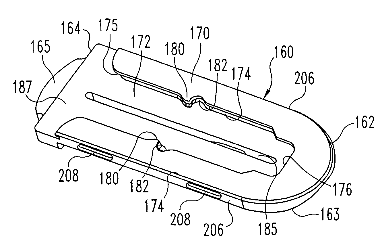
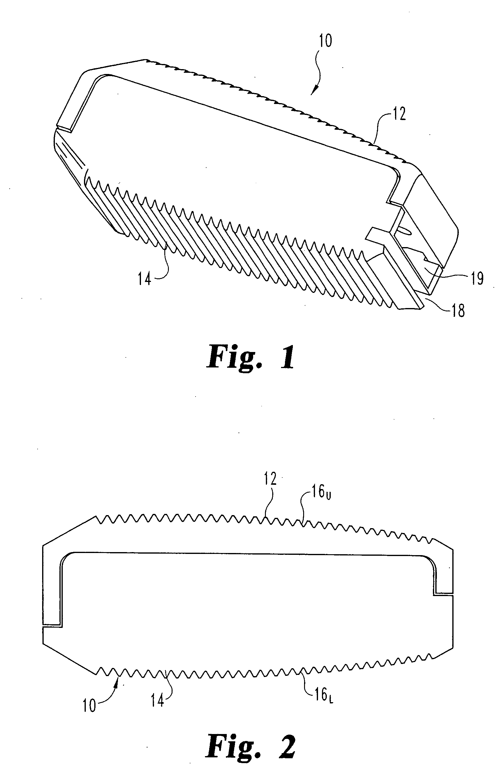
[0075] In accordance with one embodiment of the invention, an expandable distraction device in the form of an interbody fusion device (IBFD) 10 includes a superior endplate 12 and an inferior endplate 14 that define a wafer cavity 19, as shown in FIGS. 1-2. The superior and inferior surfaces of the endplates define engagement ribs 16U and 16L that are configured to engage or grip the vertebral endplates of opp...


PUM


Abstract

An expandable interbody fusion device includes superior and inferior plates that are configured to receive a sequentially inserted stack of expansion members or wafers. The superior and inferior plates include features that at least initially interlock the two plates until the superior plate is dislodged by pressure from the growing wafer stack. The wafers include features on their top and bottom surfaces that interlock the wafers in multiple degrees of freedom so that the wafer stack is not disrupted when the fusion device is fully expanded. Each wafer also includes features that interlock with the inferior plate until the wafer id dislodged by sequential introduction of another wafer.

Description

REFERENCE TO RELATED APPLICATION [0001] This application claims priority to co-pending provisional application No. 60 / 604,422, filed on Aug. 25, 2004, and entitled “Expandable Interbody Fusion Device”. The disclosure of this provisional application is incorporated herein by reference.BACKGROUND OF THE INVENTION [0002] The present invention relates to devices and methods for distraction and stabilization of tissue surfaces, and most particularly for stabilization of the intervertebral disc space. [0003] The number of spinal surgeries to correct the causes of low back pain has steadily increased over the last several years. Most often, low back pain originates from damage or defects in the spinal disc between adjacent vertebrae. The disc can be herniated or can be suffering from a variety of degenerative conditions, so that in either case the anatomical function of the spinal disc is disrupted. The most prevalent surgical treatment for these types of conditions has been to fuse the tw...

Claims


Application Information

Patent Timeline
Patent Type & Authority Applications(United States)
IPC IPC(8): A61B17/58
CPCA61B2017/0256A61F2/442A61F2/4465A61F2/447A61F2/4611A61F2002/30383A61F2002/30492A61F2002/3052A61F2002/30556A61F2002/30599A61F2002/30601A61F2002/30904A61F2220/0025A61F2250/0009A61F2250/0063A61F2/4455A61F2/4425A61F2002/30476A61F2002/448
Inventor LANDRY, MICHAELWYSOCKI, STEVE
Owner SPINEWAVE
Why Eureka
Try Eureka