Controller and operating system
a controller and operating system technology, applied in the field of controllers and operating systems, can solve the problems of difficult to guarantee real-time execution, difficult to predict the length of processor time assigned, and significant challenges in the size and cost reduction of controllers, so as to achieve the effect of easy guarantee of throughput and minimum execution tim
- Summary
- Abstract
- Description
- Claims
- Application Information
AI Technical Summary
Benefits of technology
Problems solved by technology
Method used
Image
Examples
second embodiment
Task Group Suspension / Resumption
(Task group Execution Mode Switching)
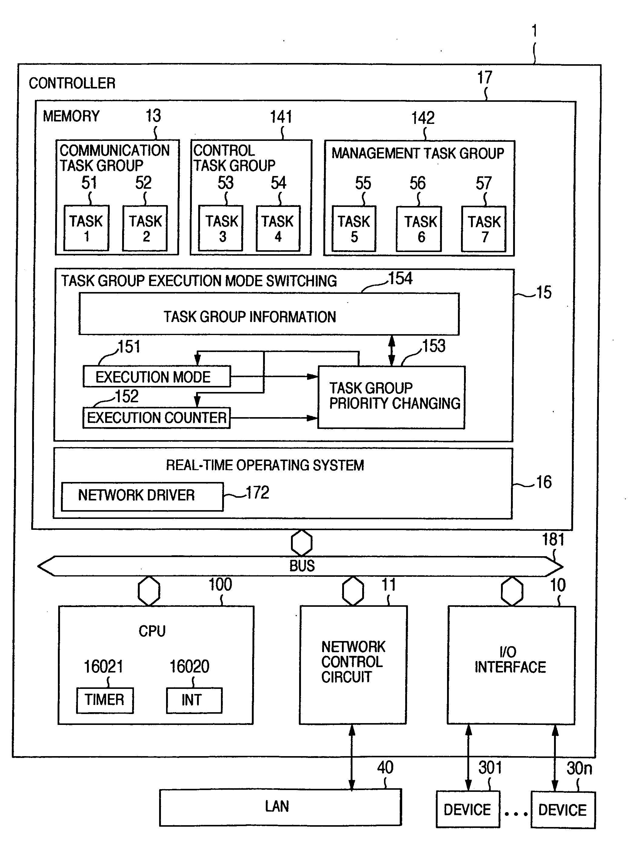
[0122] Next, description is made of a second embodiment of a task group execution mode switching 15.
[0123]FIG. 11 shows the second embodiment of the task group execution mode switching 15.
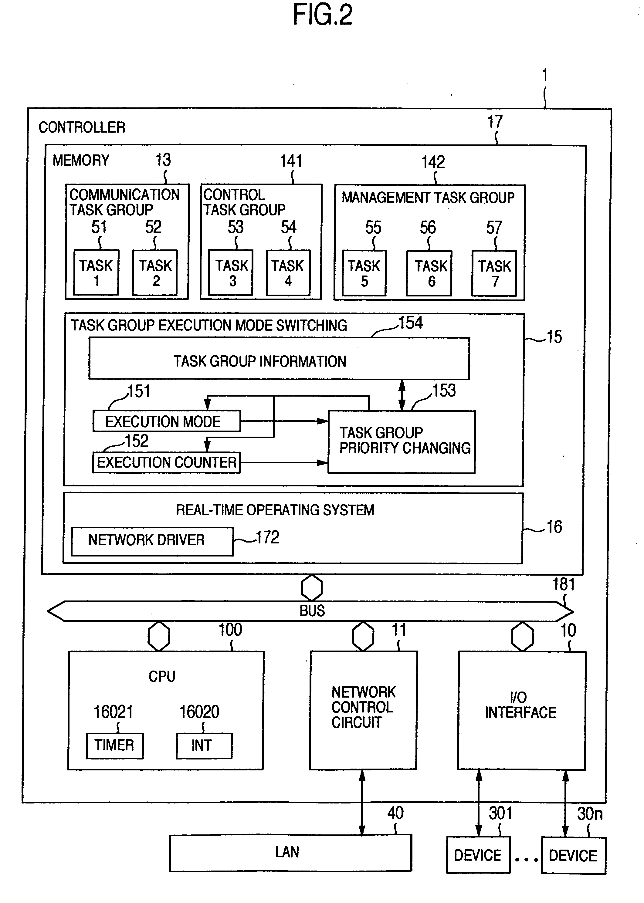
[0124] The task group execution mode switching 15 includes an execution mode 151, an execution counter 152, a task group suspension / resumption processing 1531, and task group information 154. That is, the second embodiment is different from the first embodiment of the task group execution mode switching 15 of FIG. 2 in that the task group priority changing 153 is replaced by the task group suspension / resumption processing 1531. The other components 151, 152 and 254 are similar to those of the first embodiment.
[0125] However, a content of a mode to he managed by the execution mode 151 becomes similar to that of FIG. 12. That is, on the execution mode 151, task group execution suspension / resumption form several patterns of exe...
specific example
[0141] The above-described operation is now described by way of specific example.
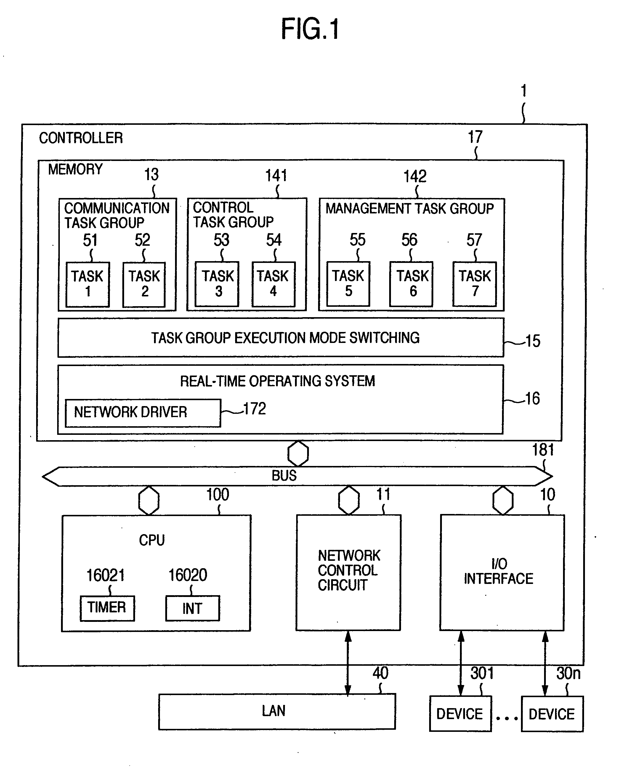
[0142]FIG. 14 shows an execution state of a task on each mode, as a result of changes made in the execution states of the totally seven tasks 1 to 7 of FIG. 1 by the operation of the task group execution mode switching 15 during mode switching of FIG. 12. In FIG. 14, suspension means one of forcible standby states (SUSPENDED or WAITING-SUSPENDED). This is equivalent to, when a need arises to suspend a task because of mode switching, any one of the following states, in which the task has been, i.e., an execution state (RUNNING), an executable state (READY) and a standby state (WAITING). Conversely, execution means a return of a task state to one selected from RUNNING, READY and WAITING. In a dormant state of a task (DORMANT), no state changes are made irrespective of task suspension / execution.
[0143] Execution states of the task groups on respective modes are as follows: [0144] (1) Mode 0: a communicati...
third embodiment
Task Group Priority Control
[0158]FIG. 16 shows a configuration example of a controller of the invention, focusing on a hardware configuration.
[0159] The controller 1 comprises a CPU 100, a memory 17, a PHY module 182, and a network interface 183. The memory 17, and the CPU 100 are connected to an external bus 181. The CPU 100 includes a CPU core 1001, a timer 16021, an interruption control circuit (INT in the drawing) 16020, an I / O interface 10, and a communication controller medium nondependent portion 110. the CPU core 1001, the communication controller medium non-dependent portion 110, an the I / O interface 10 are connected to an internal bus 1002.
[0160] Here, the PHY module 182 is a transceiver for achieving a network physical layer.
[0161] The communication controller medium non-dependent portion 110, the PHY module 182, and the network interface 183 constitute the network control circuit shown in FIG. 1.
[0162] The controller 1 is connected to a LAN 40 by the network interfa...
PUM
 Abstract
Description
Claims
Application Information
 - R&D
- Intellectual Property
- Life Sciences
- Materials
- Tech Scout
- Unparalleled Data Quality
- Higher Quality Content
- 60% Fewer Hallucinations
Browse by: Latest US Patents, China's latest patents, Technical Efficacy Thesaurus, Application Domain, Technology Topic, Popular Technical Reports.
© 2025 PatSnap. All rights reserved.Legal|Privacy policy|Modern Slavery Act Transparency Statement|Sitemap|About US| Contact US: help@patsnap.com


