
Multi-thread processor and its hardware thread scheduling method

a multi-thread processor and hardware thread technology, applied in the direction of instruments, program control, computation using denominational number representation, etc., can solve the problems of inability to flexibly establish the execution time of threads, inability to process threads with lower priorities, and inability to allocate sufficient execution time to threads with higher priorities. , to achieve the effect of flexible execution time of hardware threads

Active Publication Date: 2013-01-10
RENESAS ELECTRONICS CORP
View PDF10 Cites 0 Cited by
  • Summary
  • Abstract
  • Description
  • Claims
  • Application Information

AI Technical Summary

Benefits of technology

The present invention relates to a multi-thread processor and its hardware scheduling method. The technical effect of the invention is that it allows for flexible and efficient selection of hardware threads for execution based on their priority rank, while ensuring minimal execution time. This prevents certain hardware threads from being fixedly selected and allows for effective use of the processor's resources.

Problems solved by technology

The present inventors have found a problem that in both of the round robin method and priority method, it is impossible to flexibly establish the execution time of threads while ensuring the minimum execution time of the threads.
For example, in the round-robin method, when the number of threads is increased, the execution time is reduced uniformly for each thread, and thus causing a problem that sufficient execution time cannot be allocated to threads having higher priorities.
Meanwhile, the priority method has a problem that when processing for threads having higher priorities continues, thread having lower priorities cannot be processed.

Method used


Image

  • Multi-thread processor and its hardware thread scheduling method
  • Multi-thread processor and its hardware thread scheduling method
  • Multi-thread processor and its hardware thread scheduling method

Examples


first exemplary embodiment

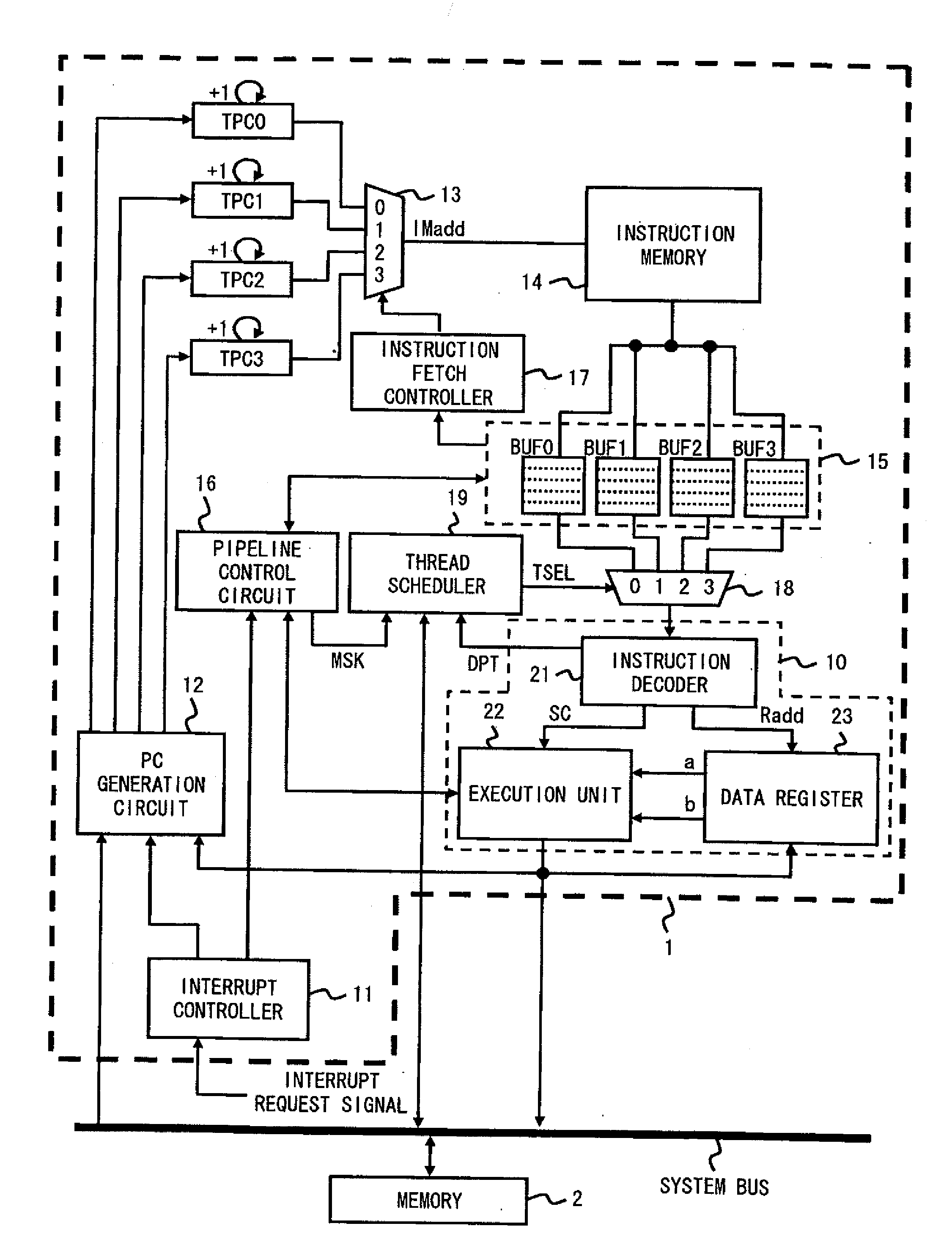
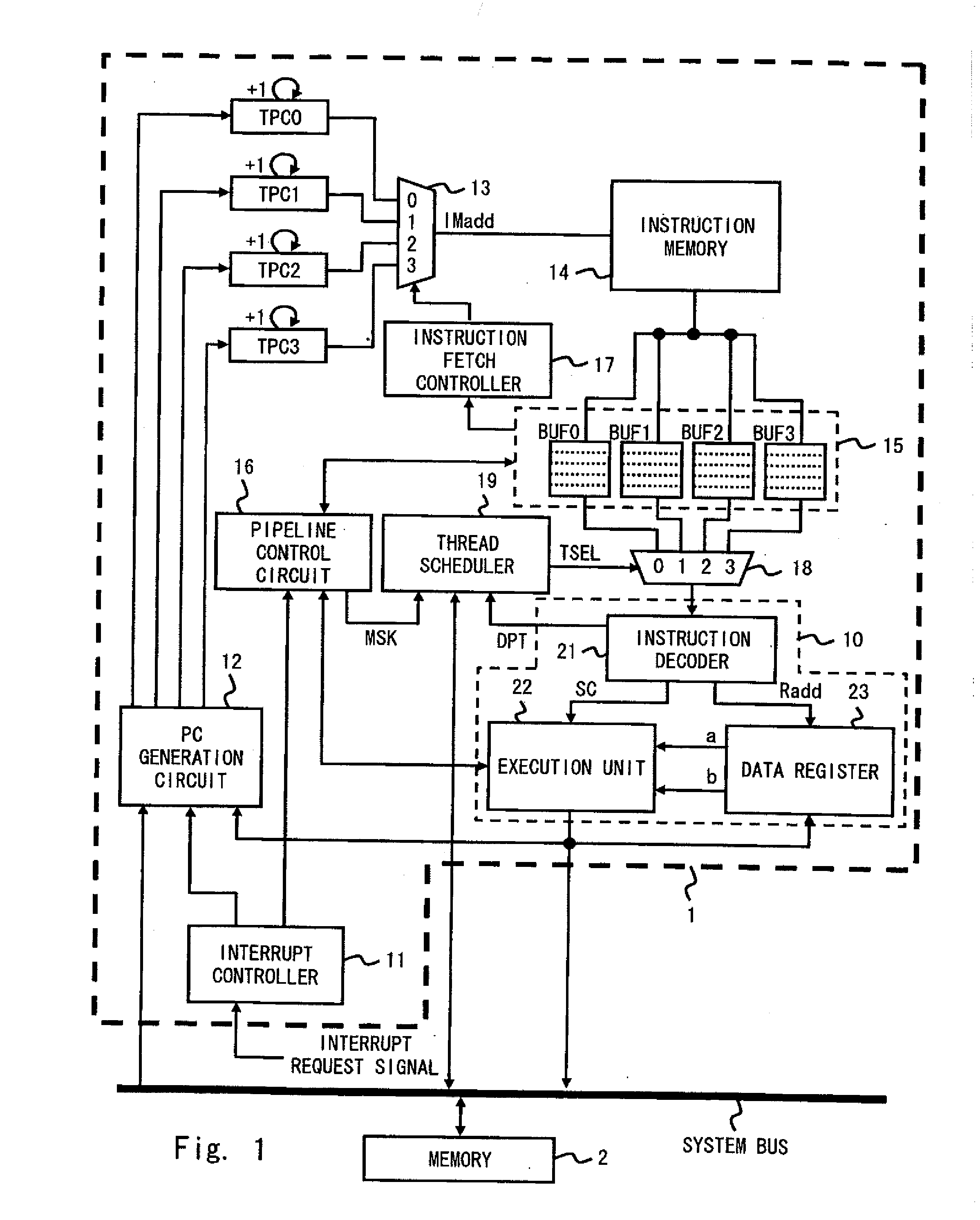
[0030]Exemplary embodiments of the present invention are explained hereinafter with reference to the drawings. FIG. 1 is a block diagram of a processor system including a multi-thread processor 1 in accordance with a first exemplary embodiment of the present invention. A multi-thread processor 1 is connected to a memory 2 through a system bus in a processor system in accordance with this exemplary embodiment. Note that though they are not shown in the figure, other circuits such as input / output interfaces are also connected to the system bus.

[0031]Firstly, a multi-thread processor 1 in accordance with this exemplary embodiment of the present invention is explained hereinafter. The multi-thread processor 1 includes a plurality of hardware threads. The hardware threads are composed of a group of circuits including thread program counters, an instruction memory, a general register, and a control register (it is assumed to be embedded in a pipeline control circuit 16 in this exemplary e...

second exemplary embodiment

[0078]FIG. 11 shows a block diagram of a multi-thread processor 1a in accordance with a second exemplary embodiment of the present invention. As shown in FIG. 11, the multi-thread processor 1a is modified from the first exemplary embodiment by replacing the thread scheduler 19 with a scheduler 19a, i.e., a modified example of the thread scheduler 19. Therefore, the following explanation is made with emphasis on the thread scheduler 19a, and explanation of other components is omitted.

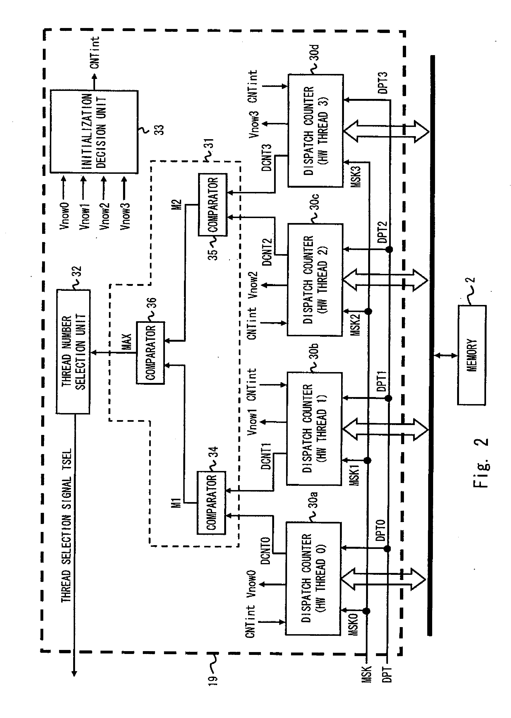
[0079]FIG. 12 shows a block diagram of the thread scheduler 19a. As shown in FIG. 12, the thread scheduler 19a includes a third selector (e.g., selector 50), a first thread scheduler 19, and a second thread scheduler 51. The selector 50 selects one of a first thread selection signal TSELa output from the first thread scheduler 19 and a second thread selection signal TSELb output from the second thread scheduler 51 according to the signal level of the real-time bit signal, and outputs the selected thread ...


PUM


Abstract

A multi-thread processor includes a plurality of hardware threads each of which generates an independent instruction flow, a first thread scheduler that outputs a first thread selection signal, the first thread selection signal designating a hardware thread to be executed in a next execution cycle among the plurality of hardware threads according to a priority rank, the priority rank being established in advance for each of the plurality of hardware threads, a first selector that selects one of the plurality of hardware threads according to the first thread selection signal and outputs an instruction generated by the selected hardware thread, and an execution pipeline that executes an instruction output from the first selector. Whenever the hardware thread is executed in the execution pipeline, the first scheduler updates the priority rank for the executed hardware thread and outputs the first thread selection signal in accordance with the updated priority rank.

Description

CROSS REFERENCE TO RELATED APPLICATIONS[0001]The present application is a Continuation of U.S. patent application Ser. No. 12 / 585,879, filed on Sep. 28, 2009, which is based on Japanese Patent Application No. 2008-252234, filed on Sep. 30, 2008, the entire contents of which is incorporated herein by reference.BACKGROUND[0002]1. Field of the Invention[0003]The present invention relates to a multi-thread processor and its hardware thread scheduling method, and in particular to a multi-thread processor having a thread scheduler that schedules the execution order of a plurality of hardware threads and its hardware thread scheduling method.[0004]2. Description of Related Art[0005]In recent years, multi-thread processors have been proposed in order to improve the processing power of processors. A multi-thread processor has a plurality of threads each of which generates an independent instruction flow. Further, the multi-thread processor performs arithmetic processing while changing the in...

Claims


Application Information

Patent Timeline
Patent Type & Authority Applications(United States)
IPC IPC(8): G06F9/38
CPCG06F9/3851G06F9/5027G06F2209/507G06F9/3857G06F9/3838G06F9/3858
Inventor ADACHI, KOJIOOMOTO, TEPPEI
Owner RENESAS ELECTRONICS CORP
Learn More