Vehicular automatic transmission and automatic selector thereof
a technology of automatic transmission and selector, which is applied in the direction of mechanical control devices, instruments, process and machine control, etc., can solve the problems of reducing the operability of the operation, so as to reduce eliminate the risk of erroneous operations, and less tendency to interfere with each other
- Summary
- Abstract
- Description
- Claims
- Application Information
AI Technical Summary
Benefits of technology
Problems solved by technology
Method used
Image
Examples
first embodiment
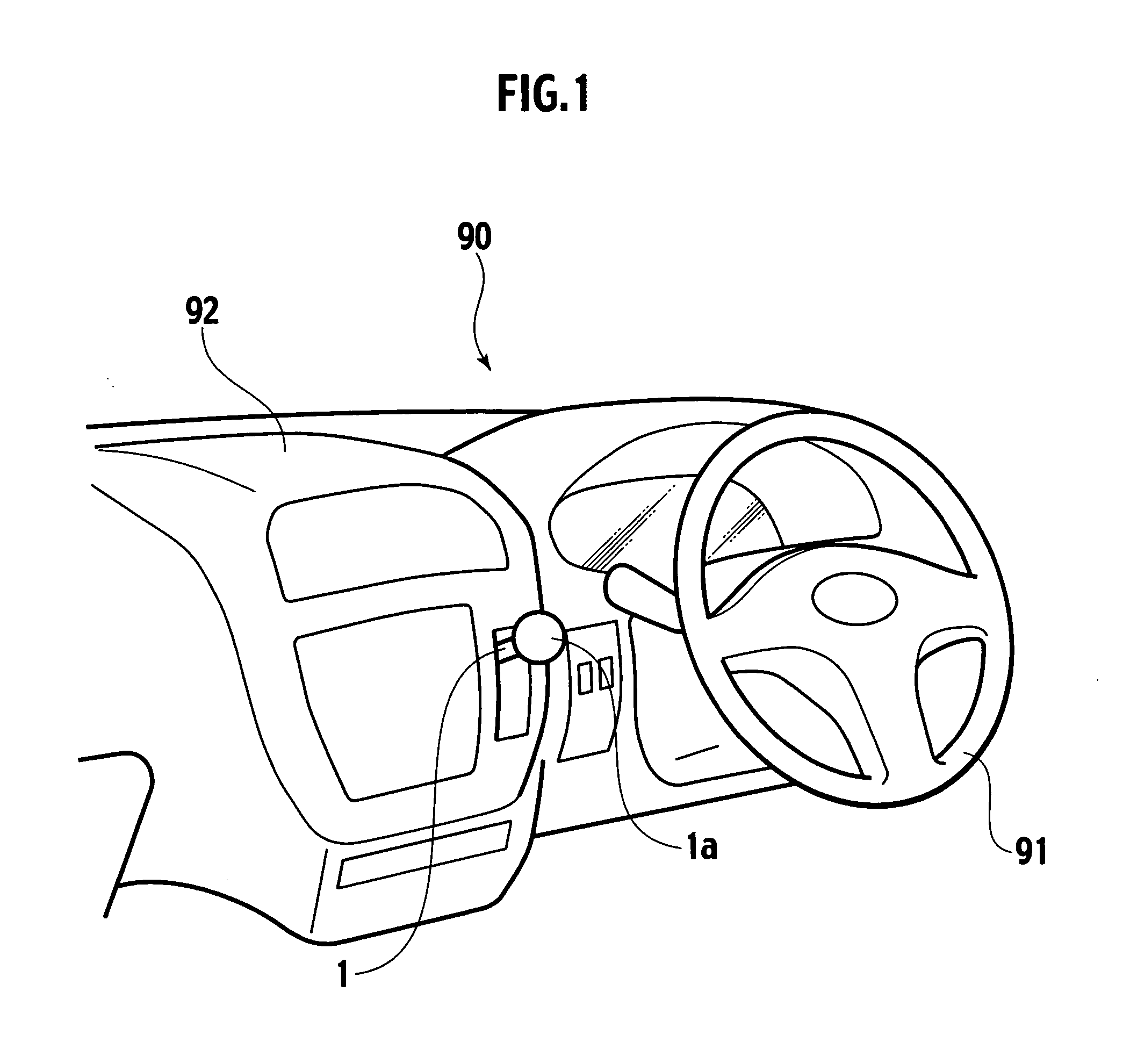
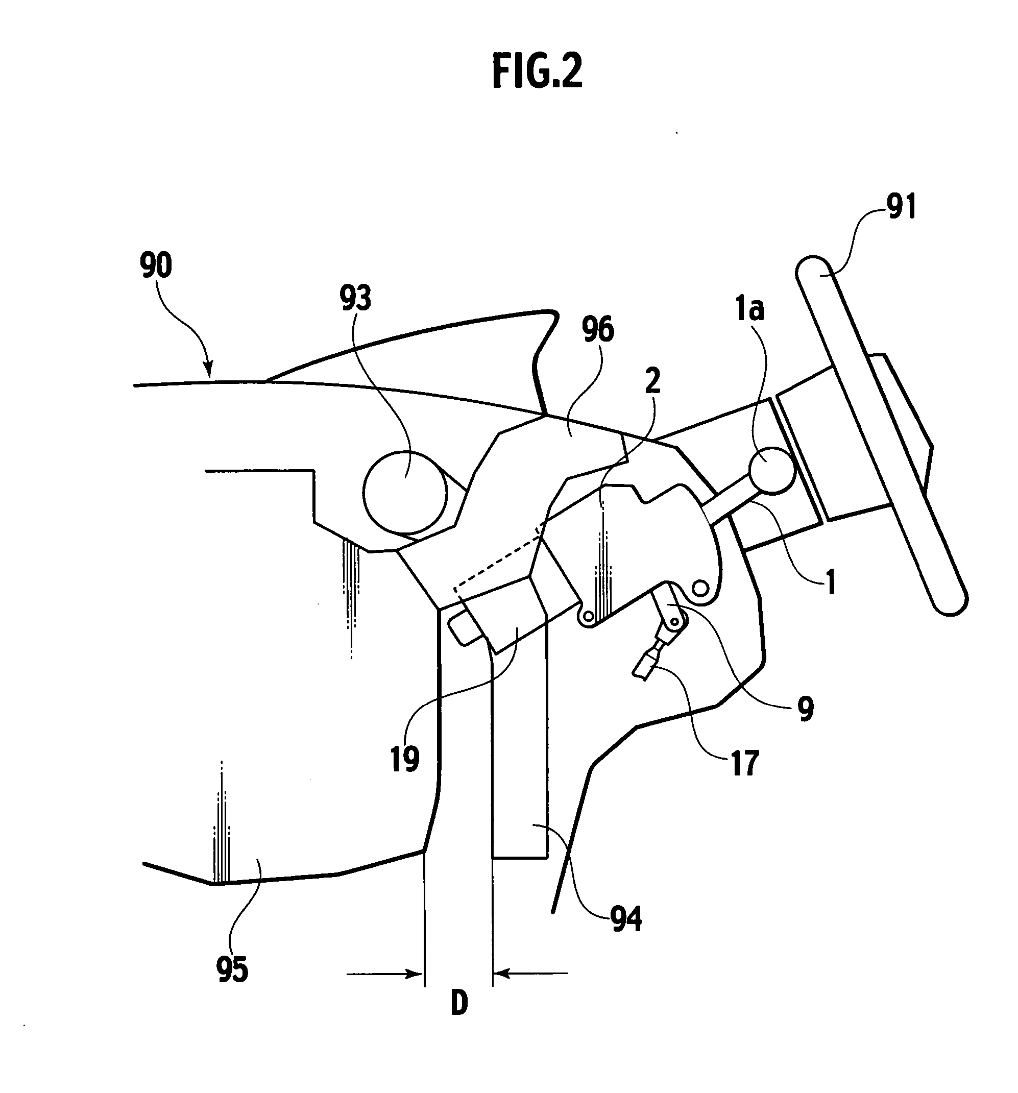
[0111] With reference to FIGS. 1 to 8, an instrument panel 90 includes a steering wheel 91 on the side of a driver's seat. A center console 92 located at a central portion of the instrument panel 90 in a widthwise direction of the vehicle slightly projects inward of a passenger room as compared with other portions.
[0112] With reference to FIG. 1, the center console 92 has a control device 2 disposed therein. The control device 2 includes a casing 5 having a two-piece separation structure. The casing 5 is provided therein with an operation lever 1 that projects inward of the passenger room. The operation lever 1 is vertically operatable for switching ranges. The operation lever 1 is shorter and more compact than that of a conventional operation lever. Therefore, the operation lever 1 has a small projecting amount in the passenger room space, and the operation lever 1 does not deteriorate the flexibility of the interior layout of the passenger room.
[0113] With reference to FIG. 2, t...
second embodiment
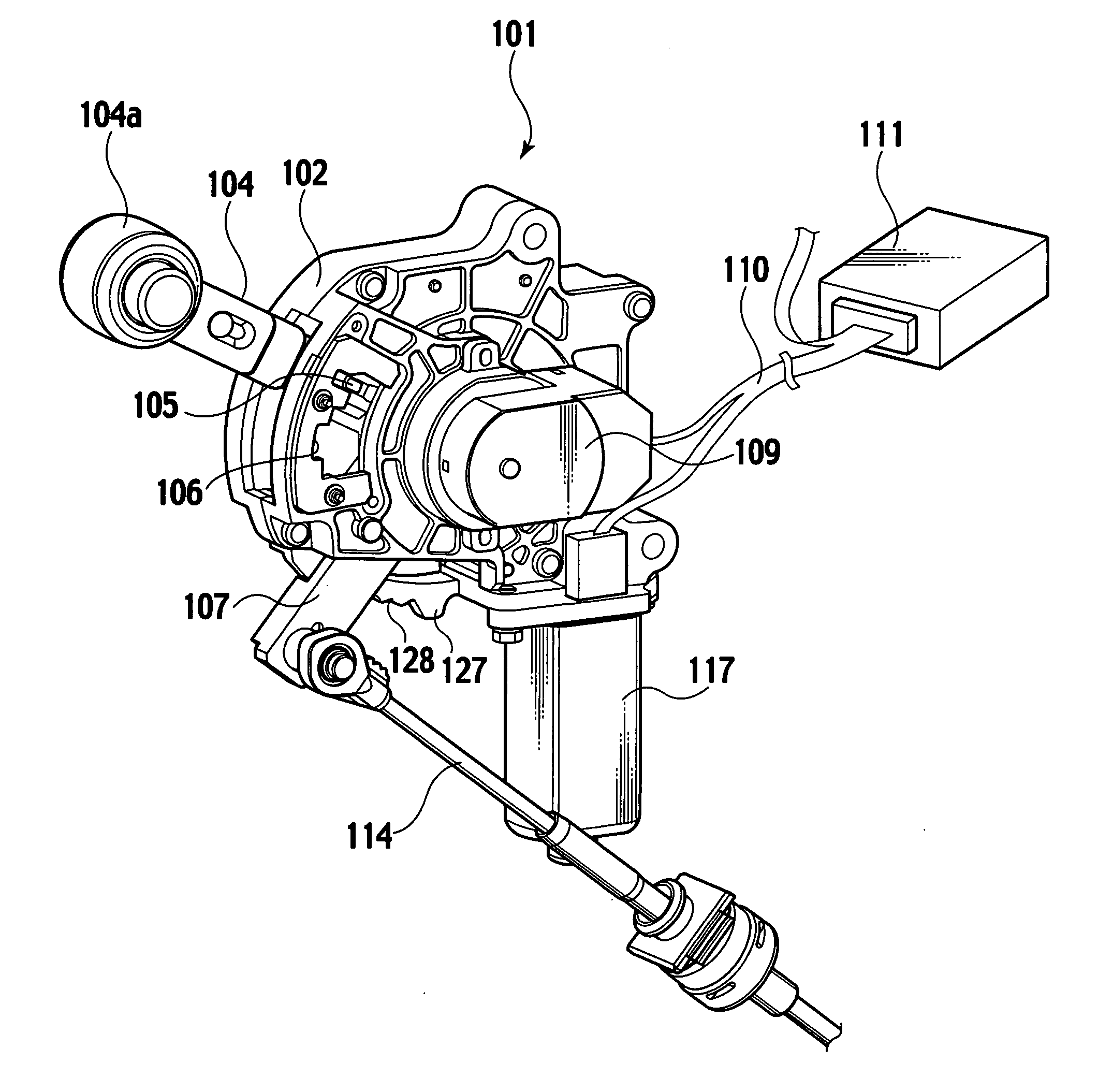
[0130] With reference to FIGS. 9 to 11, the rotation shaft 3 of the operation lever 1 is inserted into and coupled to the proximal end of the operation lever 1, with the rotation shaft 3 inserted into the bearing 10 of the output lever 9. The bearing 10 has a projection 27 in a U-shaped cross section formed thereto from the outside along the operation lever 1.
[0131] The projection 27 has opposed walls having therebetwen a distance or a space greater than the diameter of the proximal end of the operation lever 1. The projection 27 and the operation lever 1 have a rotation angle difference generator B4 therebetween, thus serving as an angular cam mechanism.
[0132] According to this embodiment, the projection 27 formed on the bearing 10 of the output lever 9 and the proximal end of the operation lever 1 have therebetween the engagement point that is located away from the rotation shaft 3. The position is advantageous when the operation force is manually transmitted from the operation ...
third embodiment
[0133] With reference to FIGS. 12 to 15, the distal end of the second lever portion 29 of an output lever 28 is formed with an exchangeable third lever portion 30. The third lever portion 30 is mounted on the second lever portion 29 using a bolt 31. Engagement of a groove 32 and a pin 33 with each other prevents the third lever portion 30 from rotating.
[0134] The operation lever 34 has, on the side thereof, an extended portion 35 extending in a direction along the second lever portion 29. The extended portion 35 has a hole 36. The bolt pin 31a is inserted into the hole 36. The bolt pin 31a is coupled to the end of the bolt 31 that mounts the third lever portion 30 on the second lever portion 29. The hole 36 and the end of the bolt pin 31a constitute a rotation angle difference generator B5 therebetween, thus serving as an angular cam mechanism.
[0135] According to this embodiment, the second lever portion 29 of the output lever 28 and the extended portion 35 provided on the side of...
PUM
 Abstract
Description
Claims
Application Information
 - R&D
- Intellectual Property
- Life Sciences
- Materials
- Tech Scout
- Unparalleled Data Quality
- Higher Quality Content
- 60% Fewer Hallucinations
Browse by: Latest US Patents, China's latest patents, Technical Efficacy Thesaurus, Application Domain, Technology Topic, Popular Technical Reports.
© 2025 PatSnap. All rights reserved.Legal|Privacy policy|Modern Slavery Act Transparency Statement|Sitemap|About US| Contact US: help@patsnap.com


