Control arm with two parallel branches

a technology of control arm and parallel branch, which is applied in the direction of programmed manipulators, manipulators, belts/chains/gearings, etc., can solve the problems of many unsuitable applications, and achieve the effect of reducing the number of collisions

Inactive Publication Date: 2006-03-23
RIWAN ALAIN +1
View PDF5 Cites 10 Cited by
  • Summary
  • Abstract
  • Description
  • Claims
  • Application Information

AI Technical Summary

Benefits of technology

[0008] It can be concluded from these various comments that arms in parallel are attractive as master arms due to the convenience in handling them, but their specific defects actually make many of them unsuitable for this application. The invention relates to a particular arrangement of arms in parallel, in which the main advantages are a large reduction in the number of collisions between the different bodies of the robot and singularities. The result is ease of control, so that the movement required to reach the required state can be imposed on them without difficulty.
[0009] These objectives are achieved with an arm with branches in parallel and with a special configuration; in its most general form, the invention relates to a robot arm composed of articulated segments distributed into two branches connected by a wrist, and the branches are made so as to extend from a common base in two halves on opposite sides of a separation plane when the said plane intersects the wrist, and they comprise corresponding segments connected to the base that extend in opposite directions from the base. Advantageously, the number of segments is the same in each branch; they can still be similar and symmetric if the segments switched to the base are co-linear with each other. In all cases, the branches are well separated from each other for almost all movements applied to the wrist, which almost completely eliminates collisions between the branches.

Problems solved by technology

It can be concluded from these various comments that arms in parallel are attractive as master arms due to the convenience in handling them, but their specific defects actually make many of them unsuitable for this application.

Method used


Image

  • Control arm with two parallel branches
  • Control arm with two parallel branches
  • Control arm with two parallel branches

Examples


Embodiment Construction

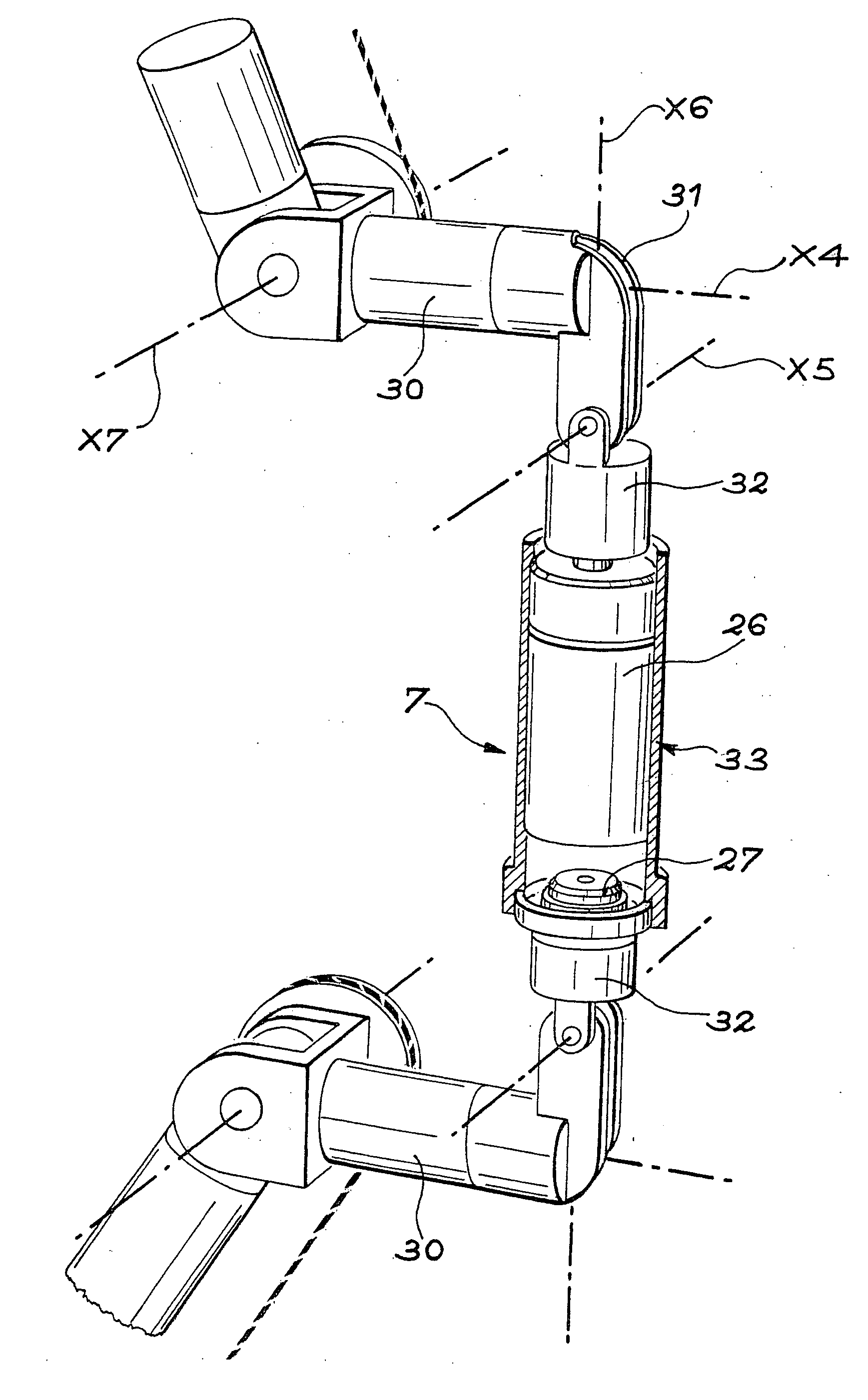
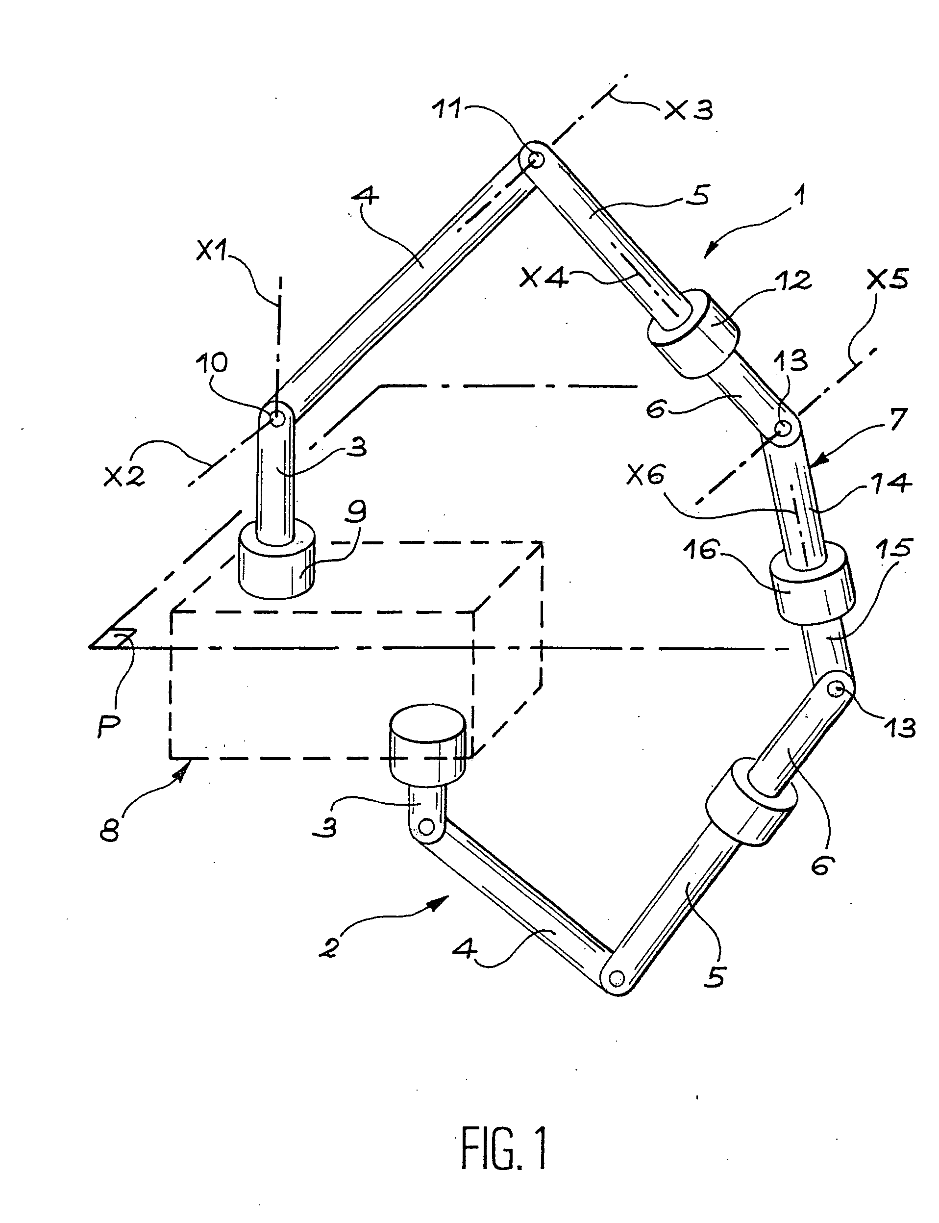
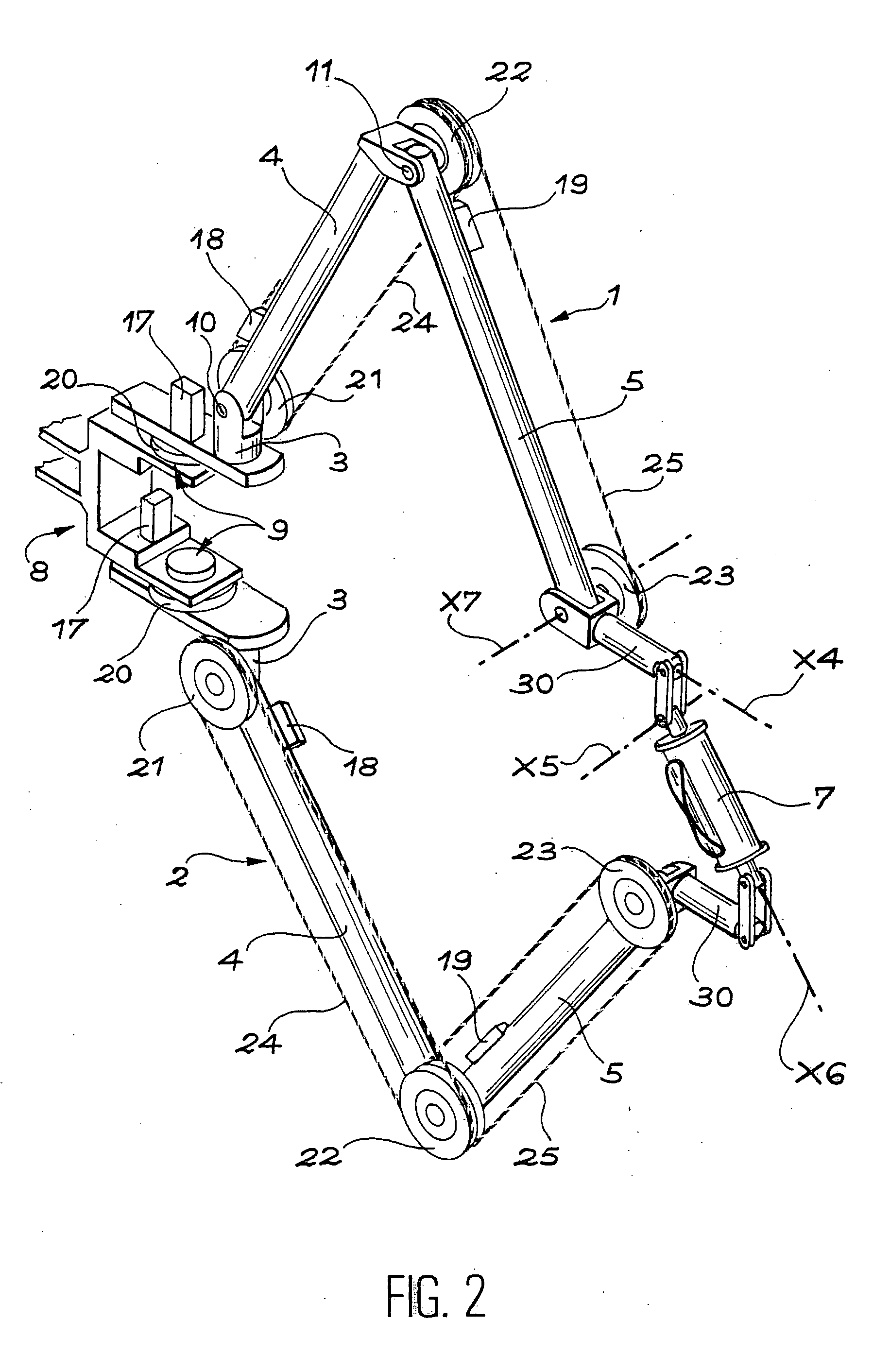
[0018] With reference to FIG. 1, it can be seen that the arm is composed of an upper branch 1 and a lower branch 2, each of which is composed of a first vertical segment 3 (the said segments 3 extending in opposite directions from a common base 8), a second segment 4, a third segment 5, a fourth segment 6, and a wrist 7 connecting the ends of the two fourth segments 6 together. The articulations successively connect the segments to each other and to the wrist, and to the common base 8 as follows: a rotary articulation with axis X1 in line with the first segment 3 and marked with reference 9 connects the first segment 3 to the common base 8; a swiveling articulation with axis X2 perpendicular to the previous axis connects the first segment 3 and the second segment 4; another swiveling articulation 11 with axis X3 parallel to the previous axis connects the second segment 4 to the third segment 5; a rotary articulation 12 with axis X4 co-linear with the third segment 5 and the fourth s...


PUM


Abstract

The master arm includes two parallel branches (1, 2), preferably symmetric, joining together at a control wrist (7). The branches are formed of segments (3, 4, 5, 6), the first (3) of which extend from a common base (8), and moving away from the base such that the branches move apart from each other and prevent the appearance of kinetic singularities.

Description

RELATED U.S. PATENT APPLICATIONS [0001] Benefit of priority is claimed from U.S. patent application Ser. No. 10 / 296,893 filed on Nov. 27, 2002, which is the U.S. National stage of PCT / FR01 / 01927, filed on Jun. 20, 2001, the complete disclosures of which are hereby expressly incorporated herein by this reference thereto.FIELD OF THE INVENTION [0002] The purpose of this invention is a control arm comprising two branches in parallel. BACKGROUND OF THE INVENTION [0003] The function of control arms is to transfer movements applied to them by an operator as control instructions for an instrument or a system, usually a remote robot called a slave arm or a computer simulation. When the control arm has a sufficient number of degrees of freedom, the operator can control it in translation and in rotation in space. [0004] The arms used in robotics have a very wide variety of shapes. The most traditional arms are composed of a sequence of segments connected to each other by articulations or some...

Claims


Application Information

Patent Timeline
Patent Type & Authority Applications(United States)
IPC IPC(8): B25J17/02B25J3/00B25J9/10B25J13/02F16H21/54
CPCB25J9/107Y10T74/20323B25J13/02
Inventor RIWAN, ALAINGOSSELIN, FLORIAN
Owner RIWAN ALAIN
Why Eureka
Try Eureka