
Dispenser

Inactive Publication Date: 2006-03-23
SC JOHNSON & SON INC
View PDF18 Cites 41 Cited by
  • Summary
  • Abstract
  • Description
  • Claims
  • Application Information

AI Technical Summary

Benefits of technology

[0005] the dispenser having solenoid valve means substantially enclosed in a substantially metallic locking cover means, the valve means being arranged to substantially facilitate movement of the spray

Problems solved by technology

A problem with many of the existing dispensers is

Method used


Image

  • Dispenser
  • Dispenser
  • Dispenser

Examples


Embodiment Construction

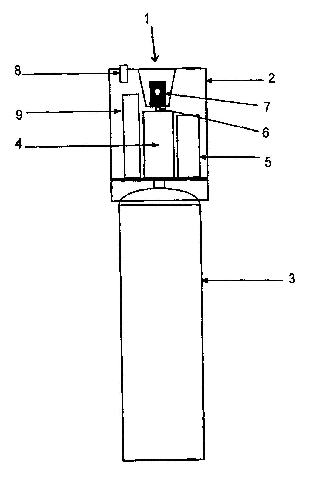
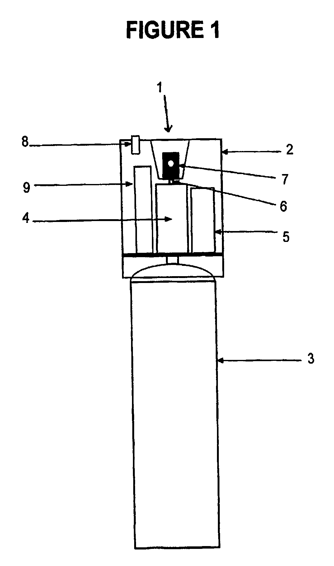
[0021] Referring to FIG. 1, the dispenser 1 comprises a dispenser head 2 and a container 3. The dispenser head 2 has a solenoid valve 4 which is powered by a small battery 5. When the valve 4 is opened it allows spray material to flow from the container 3 to be released to the atmosphere via an aperture 6 and a spray nozzle 7. The spray head 2 also has a switch 8 which can be used to activate a circuit board 9 for controlling opening and closing of the valve 4. The circuit board 9 is powered by the battery 5.

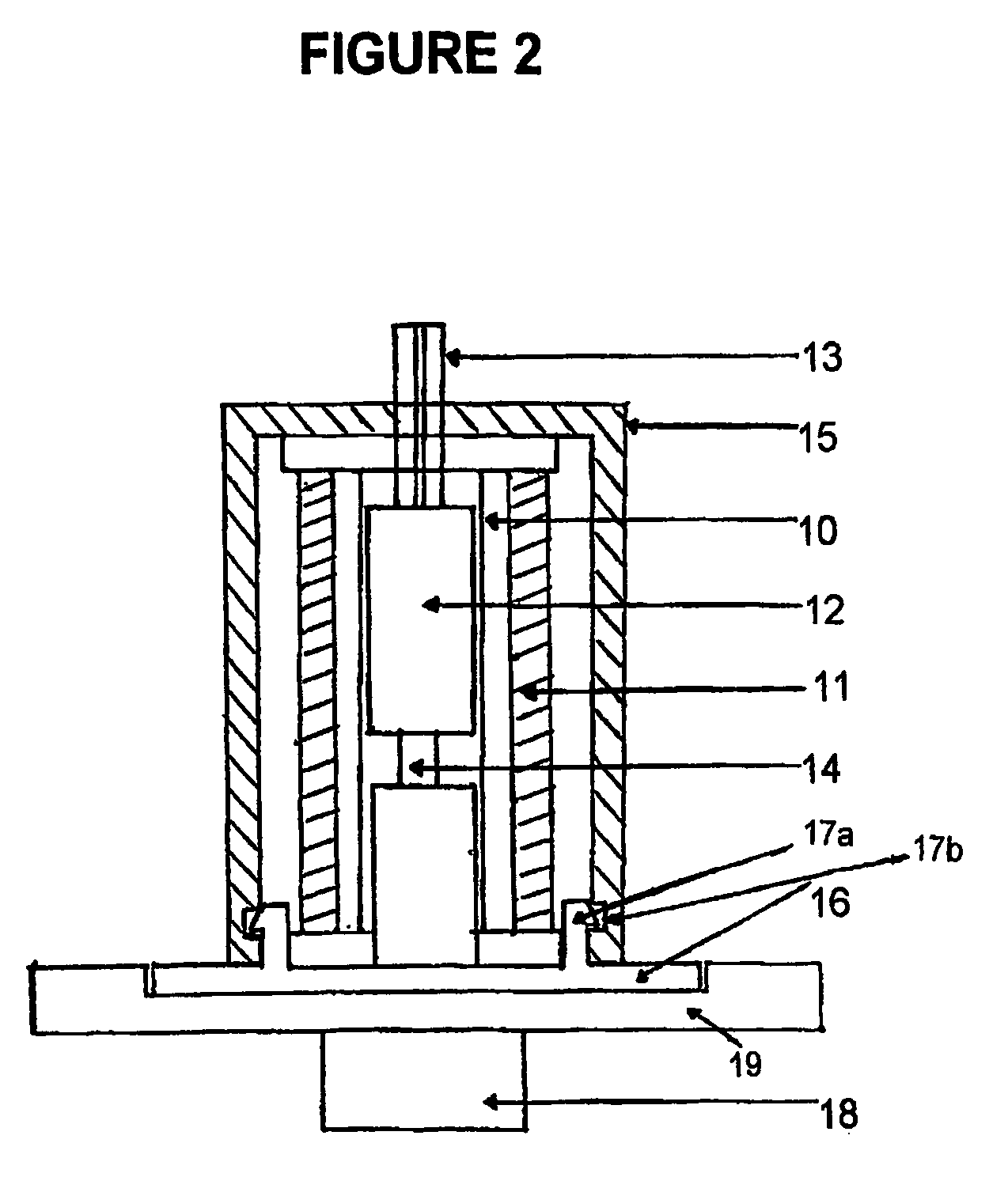
[0022] Referring to FIG. 2, the solenoid valve 4 comprises a bobbin 10 which is wound with electrical wire 11, through which an armature 12 is moveable. More particularly, the armature 12 can move when a magnetic flux is created within the bobbin 10 in response to an electrical current. It will be appreciated that when the armature 12 moves appropriately the valve 4 is momentarily opened. When the valve 4 is opened, pressurized fluid held in the container 3 is able to pass thro...


PUM


Abstract

According to the invention there is a dispenser (1), the dispenser having a dispenser head (2) and a container (3), containing spray material, the dispenser being formed such that the container (3) can be detached from the dispenser head (2) and refilled and/or replaced when the spray material is exhausted; the dispenser (1) having a solenoid valve means (4) substantially enclosed in a substantially metallic locking cover means, the valve means (4) being arranged to substantially facilitate movement of the spray material from the container (3) to the spray head (2), and the cover means being arranged to intensity a magnetic field which, when the dispenser is in use, facilitates opening and closing of the valve means. The dispenser (1) being formed such that in can be set so the valve means (4) opens and closes automatically and periodically to release a flow of spray material from the container to the spray head such that the spray material is released as a spray to an atmosphere outside of the dispenser.

Description

FIELD OF INVENTION [0001] This invention relates to a dispenser. A preferred form of the invention relates to an dispenser for automatically releasing a spray into an atmosphere intermittently. BACKGROUND ART [0002] It is known to use automatic aerosol dispensers to spray liquid agricultural chemicals, odor neutralizers, disinfectants, or essential oils, etc, into an atmosphere. In the case of agricultural chemicals these may be for the purpose of repelling or destroying insect pests. A problem with many of the existing dispensers is that they become ineffective at high temperatures. It is accordingly an object of at least one form of the present invention to go at lest some way towards addressing this problem, or to at least provide the public with a useful choice. [0003] The term “comprise”, “comprises”, “comprised” or “comprising” if and when used in this document, should be interpreted non-exclusively, i.e. should be interpreted non-exclusively to mean “consisting of or includin...

Claims


Application Information

Patent Timeline
IPC IPC(8): B67D3/00B05B12/02B65D83/14B65D83/16
CPCB05B12/02B65D83/24B65D83/75B65D83/70B65D83/262B05B12/06
Inventor MCLISKY, NIGEL HAIG
Owner SC JOHNSON & SON INC
Learn More