Multifunctional support rack

a multi-functional, support rack technology, applied in the field of support racks, can solve the problems of inconvenience for users in package, storage and transportation, inconvenient adjustment of the inclined angle of the support board, etc., and achieve the effect of reducing the volume of the support rack

Inactive Publication Date: 2006-03-23
LUH IND CORP
View PDF10 Cites 12 Cited by
  • Summary
  • Abstract
  • Description
  • Claims
  • Application Information

AI Technical Summary

Benefits of technology

[0014] A further objective of the present invention is to provide a support rack, wherein the support stand is adjustably mounted on the locking member so as to adjust the inclined angle between the support plate and the support stand, thereby facilitating a user adjusting the inclined angle of the support

Problems solved by technology

However, the joint 3 is often limited to the length of the extension arm 2, so that the inclined angle of the support board 4 cannot be freely adjusted to the optimum value to fit a user requirement, thereby causing inconvenience to the user in adjustment of the inclined angle o

Method used


Image

  • Multifunctional support rack
  • Multifunctional support rack
  • Multifunctional support rack

Examples


Embodiment Construction

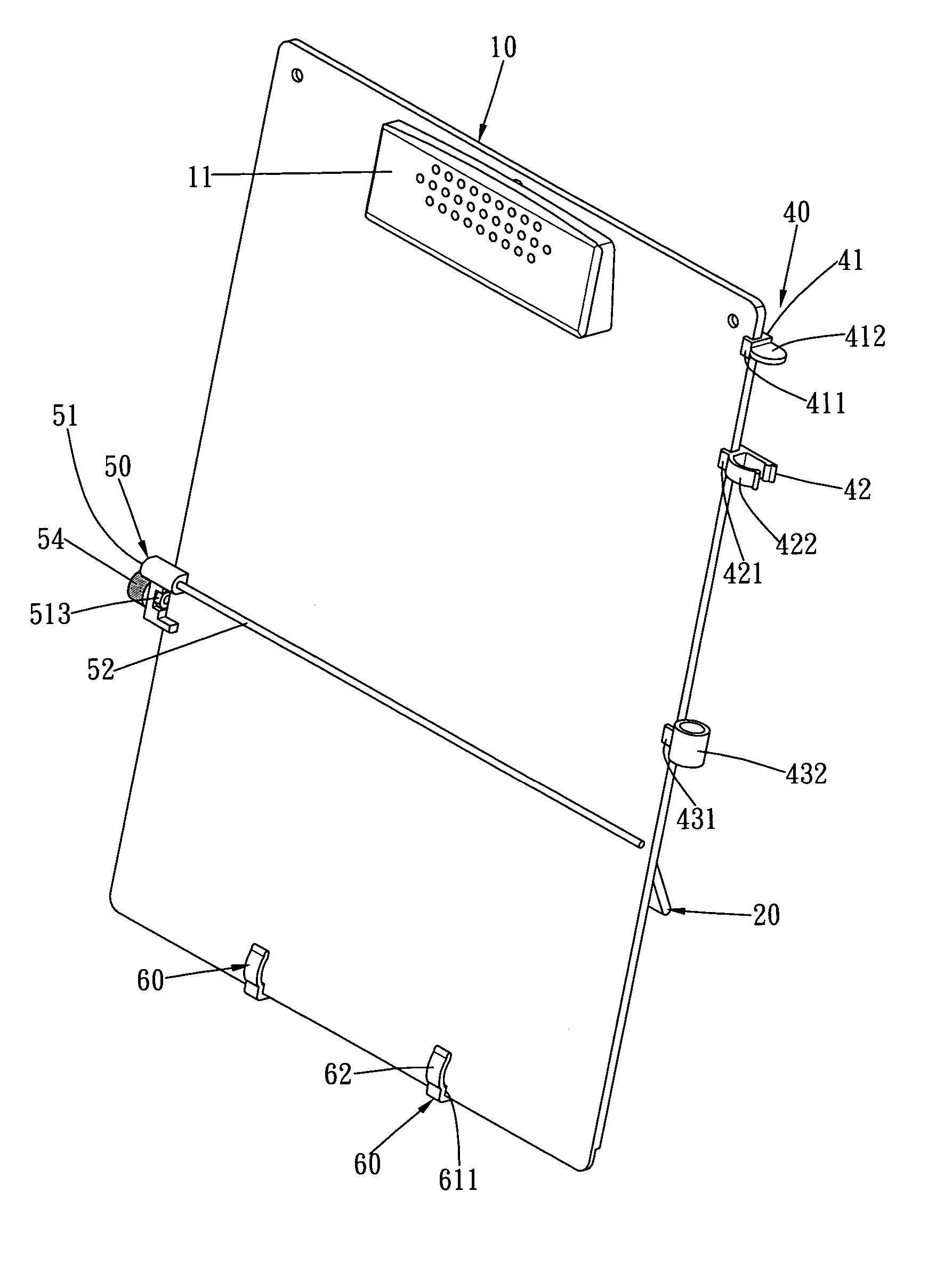
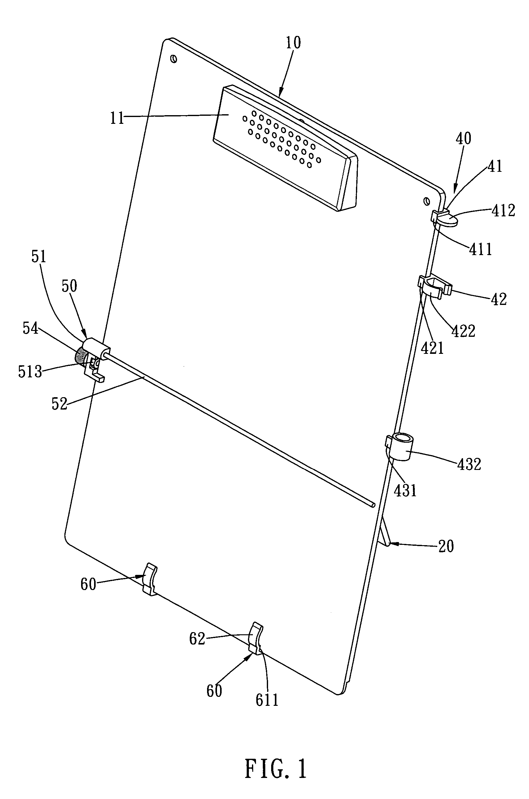
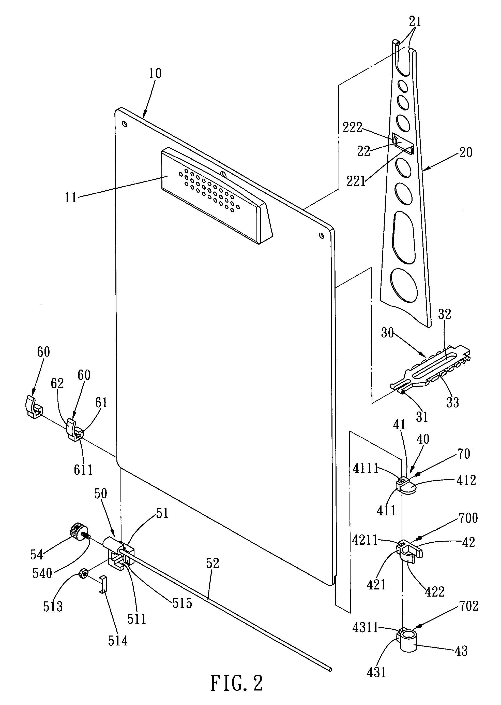
[0027] Referring to the drawings and initially to FIGS. 1-6, a support rack in accordance with the preferred embodiment of the present invention comprises a support plate 10, a support stand 20 pivotally mounted on the support plate 10, a locking member 30 pivotally mounted on the support plate 10 and detachably locked on the support stand 20 to secure the support stand 20 on the support plate 10, a pen holder 40 movably mounted on the support plate 10, an indication member 50 movably mounted on the support plate 10, and two auxiliary clips 60 each slidably mounted on the support plate 10.

[0028] The support plate 10 has a first face provided with an elastic clip 11 and a second face formed with two first pivot ears 12 and two second pivot ears 13. The second face of the support plate 10 has a periphery formed with a peripheral rib 14.

[0029] The support stand 20 has a bifurcated first end formed with two inward extended pivot shafts 21 pivotally mounted on the first pivot ears 12 o...


PUM


Abstract

A support rack includes a support plate, a support stand, a locking member, a pen holder, an indication member, and two auxiliary clips. Thus, the support rack functions as a clipboard, a book rack, an exhibition rack, a price indication rack, a pen holder or the like, thereby enhancing the versatility of the support rack. In addition, the support stand is adjustably mounted on the locking member so as to adjust the inclined angle between the support plate and the support stand, thereby facilitating a user adjusting the inclined angle of the support rack to the optimum extent.

Description

BACKGROUND OF THE INVENTION [0001] 1. Field of the Invention [0002] The present invention relates to a support rack, and more particularly to a multifunctional support rack that functions as a clipboard, a book rack, an exhibition rack, a price indication rack, a pen holder or the like. [0003] 2. Description of the Related Art [0004] A conventional support rack for a computer in accordance with the prior art shown in FIG. 10 comprises a holder 1 mounted on a table 5, an extension arm 2 mounted on the holder 1, a joint 3 pivotally mounted on the extension arm 2, and a support board 4 mounted on the joint 3 for placing paper, document or the like. However, the joint 3 is often limited to the length of the extension arm 2, so that the inclined angle of the support board 4 cannot be freely adjusted to the optimum value to fit a user requirement, thereby causing inconvenience to the user in adjustment of the inclined angle of the support board 4. In addition, the conventional support rac...

Claims


Application Information

Patent Timeline
IPC IPC(8): A47F5/00
CPCA47B97/08A47F5/16G09F3/20B43M99/001B42F9/002
Inventor HSU, FU-LU
Owner LUH IND CORP
Why Eureka
Try Eureka