

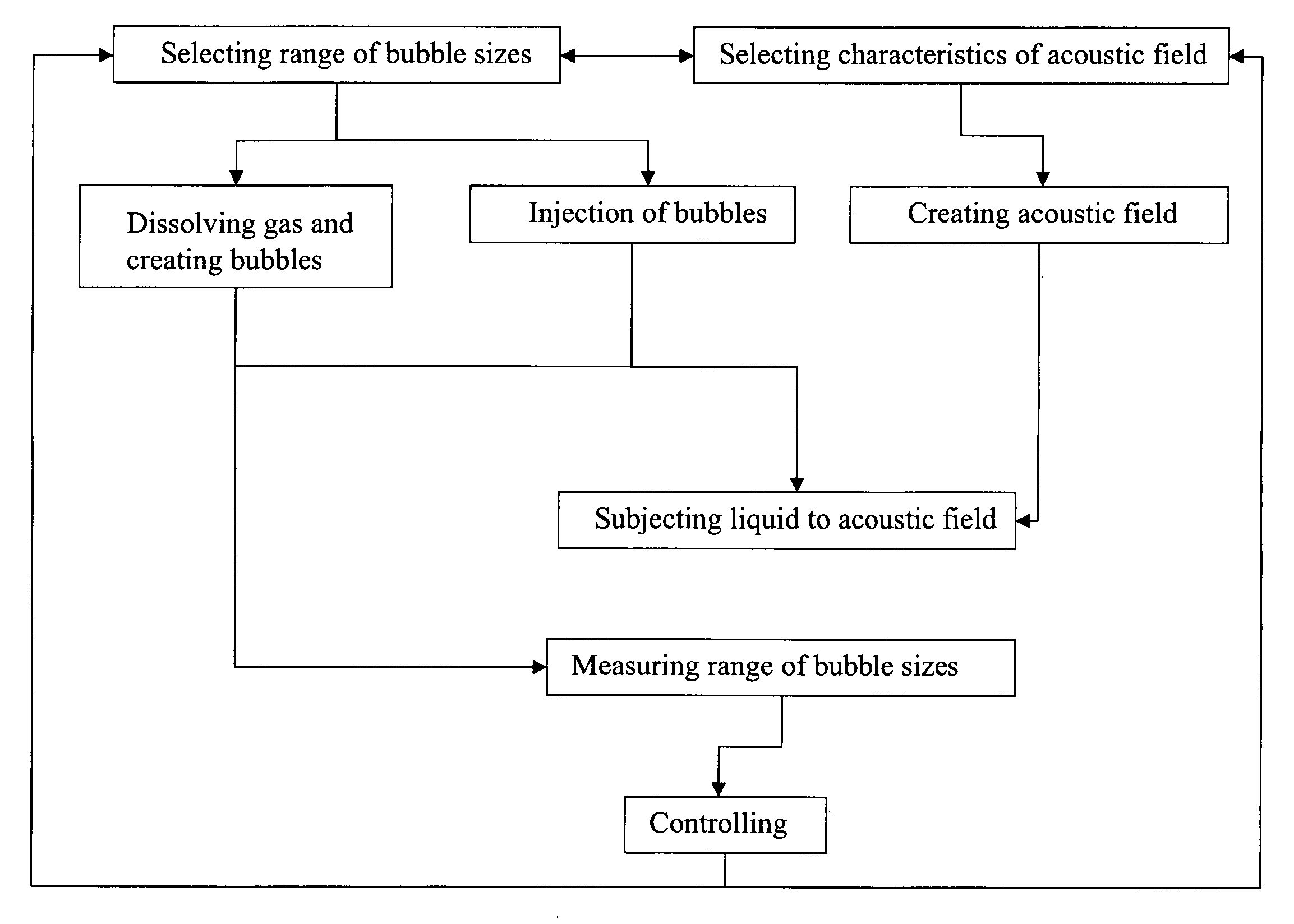
Method and apparatus for controlled transient cavitation
a transient cavitation and controlled technology, applied in the direction of cleaning processes and apparatus, cleaning using liquids, instruments, etc., can solve the problems of uniform removal of particles from substrate surfaces, difficult to achieve using current approaches, and ineffective use of megasonic energy alone for particle removal, etc., to achieve rapid pressure drop
- Summary
- Abstract
- Description
- Claims
- Application Information
AI Technical Summary
Benefits of technology
Problems solved by technology
Method used
Image

Examples
example 1
[0066] By means of the Young formula, which is based on the Rayleigh-Plesset model, the resonant radius of a bubble at a particular frequency can be calculated: ωr2=(3γ P0ρ R02)
[0067] If the frequency (φr)=1.8 MHz and ωr=2πφr, the adiabatic constant (γ) for oxygen=1.4, the density (ρ) for DIW=1000 kg / m3 and the hydrostatic pressure (P0) at 0.25 m depth=103800 Pascal, then the resonant radius is 1.85 μm. This means that in a 1.8 MHz acoustic field, even at very low acoustic pressure (e.g. 0.1 W / cm2), bubbles with a radius of 1.85 μm will collapse. At higher acoustic pressures (e.g. 10 W / cm2), a broader range of bubbles sizes close to the resonant radius will collapse as well.
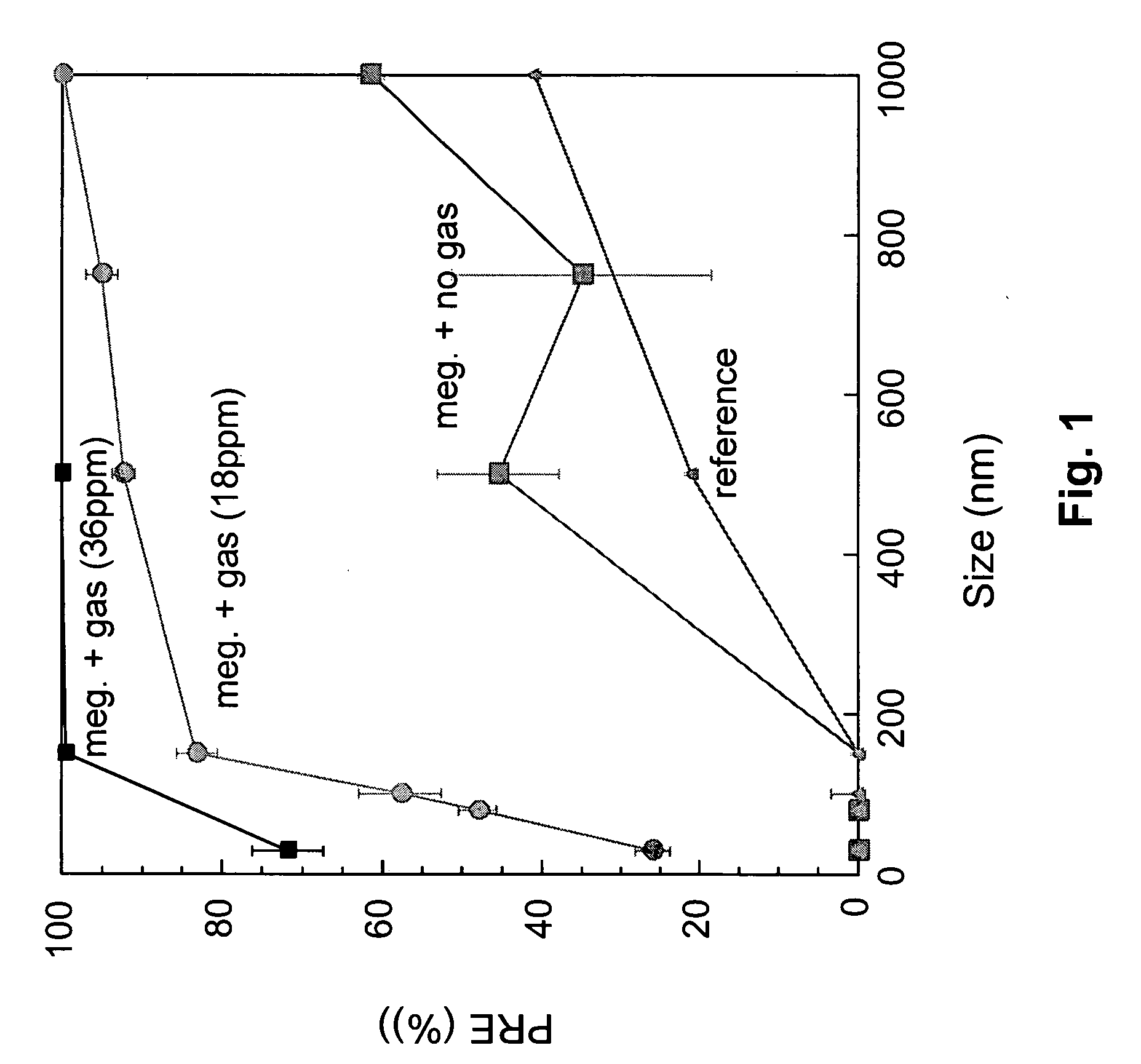
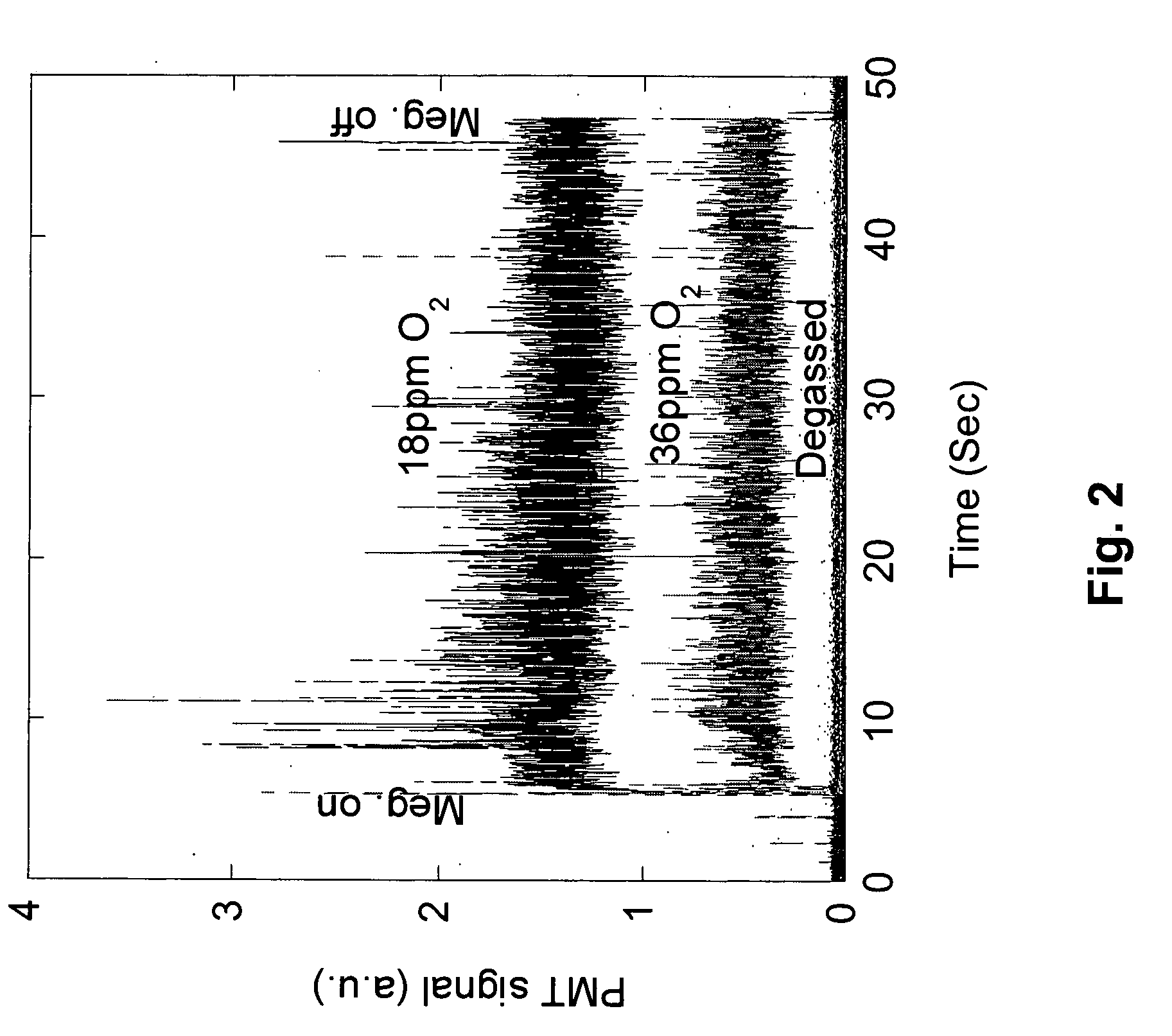
[0068] In a particular Techsonic wafer cleaning tank, an acoustic field of 1.8 MHz and 5 W / cm2 was generated. The water and gas supply system of the tank, working at 2.5 bar overpressure and containing 18 ppm oxygen after passing a Mykrolis Phasor 2 gasification unit, operated at a flow of 8 SLM with the t...
example 2
[0070] A set of silicon substrates contaminated with 34 nm SiO2-particles was used to evaluate the cleaning performance of a single wafer megasonic cleaning tool. The formation of bubbles to achieve (generate) transient cavitation, was done using a chemical supply system prior to applying a megasonic field. A backpressure regulator was used to realize a pressure drop, which created a controlled over-saturation of a specific gas, in this case argon. This process resulted in a specific bubble distribution. To obtain this bubble distribution, ultra pure water was gasified at high pressure (Pwater=2.6 bar). The amount of argon added was chosen such that the liquid was under-saturated at the 2.6 bar level (no bubbles were present), but 20% over-saturated after the pressure drop (Pwater˜1 bar). Due to the over-saturation, the excess amount of argon created a typical bubble distribution in the supply system, which is shown in FIG. 11. The generated bubble distribution was monitored by an i...
PUM
 Abstract
Description
Claims
Application Information