Apparatus for separating and storing liquid refrigerant in refrigerant circuit

a technology for refrigerant circuits and apparatuses, applied in refrigeration and liquid, lighting and heating apparatus, refrigeration machines, etc., can solve problems such as vibration and unintended noise, parts may be damaged, and the density of the product is significant, so as to reduce the risk of retardation of boiling, improve sound behavior, and reduce the effect of cos

Active Publication Date: 2020-07-14
HANON SYST
View PDF24 Cites 0 Cited by
  • Summary
  • Abstract
  • Description
  • Claims
  • Application Information

AI Technical Summary

Benefits of technology

[0008]An object of the present invention is to provide an apparatus for separating and storing liquid refrigerant, particularly an accumulator for a refrigerant circuit of a compression refrigerator, capable of reducing a risk of retardation of boiling of liquid refrigerant which is stored outside an outlet pipe or separated therefrom. In particular, the apparatus must improve sound behavior in a refrigerant circuit of a vehicle having an electric drive device, a hybrid drive device, and an internal combustion engine drive device. The apparatus must also be adapted for a heat pump system. Moreover, the apparatus must be manufactured, maintained, and installed at minimal costs.
[0013]According to an improvement of the present invention, the apparatus according to the present invention has a refrigerant supply line connected into the housing above the level of refrigerant. Preferably, the apparatus has a cover member disposed in the housing. The cover member is spaced apart from the inlet opening of the refrigerant outflow line between the refrigerant supply line and the inlet opening of the refrigerant outflow line so that the inlet opening is protected from the refrigerant introduced into the housing through the refrigerant supply line. The cover member is used to separate a liquid refrigerant and a gas refrigerant. The formation of the cover member prevents the liquid refrigerant as a water droplet from being drawn into the inlet opening of the refrigerant outflow line, which is a steam inlet, and prevents the separation and storage function of the apparatus from being deteriorated due to the introduction of the refrigerant.
[0022]The accumulator according to the present invention has an advantage of increasing the contact surface with a refrigerant present in liquid phase by the boiling element disposed in the housing. Due to the increase of the contact surface, there is a high possibility of forming steam bubbles in the liquid refrigerant, and the boiling process outside the refrigerant outflow line is introduced as intended. Therefore, the risk of retardation of boiling is reduced even though a rapid pressure drop occurs in the accumulator. As a result, the initial formation of steam bubbles is used to prevent the retardation of boiling, e.g. noise such as a sound of explosion generated in the accumulator due to the retardation of boiling. Thus, by such a manner, the unintended noise causing the retardation of boiling is prevented and the soundproof of the system is improved. In addition, it is ensured that the accumulator and the additional parts of the refrigerant circuit of the compression refrigerator have a relative low load without the sudden variation in pressure, thereby increasing the overall life of the refrigerator.
[0024]The boiling element of the accumulator may be made of a porous material or a porous material for manufacture, particularly for facilitating to form a bubble nucleus, instead of a perforated material. For example, the boiling element may be used as a sintered body having a defined porosity. In addition, metal, polymer, or ceramic may be considered as the material for manufacture. When a porous material is preferably used to manufacture the boiling element, it is possible to realize a small weight and a large contact surface with refrigerant in a small space. In this case, it is possible to facilitate the formation of steam bubbles and all materials matched with oil and refrigerant may be properly used. Preferably, the accumulator may be used for various refrigerants. The housing, the refrigerant guide lines, and the boiling element are made of a material resistant to refrigerants such as R134a, R1234yf, R1234ze, R744, R600a, R290, R152a, and R32, a mixture thereof, and oil. Aluminum or an aluminum alloy is preferable as the material. The reason is because aluminum has a high mechanical strength, a small weight, and a high durability.

Problems solved by technology

The sudden evaporation of superheated liquid refrigerant, which refers to a retardation of boiling, causes the liquid refrigerant to be suddenly changed to a gas refrigerant, which may lead to a significant decrease in density.
Such a pressure wave causes vibration and unintended noise again.
Moreover, the variation in pressure and the vibration apply a significant load to the refrigerant circuit or the parts of the compression refrigerator, and therefore the parts may be damaged.
In the retardation of boiling, typical containers, each having a high surface quality but having a small wetted surface area, has a very weak resistance.
The surface area of the pipe coming into contact with liquid refrigerant may not ensure that gas bubbles are formed enough to block an imminent retardation of boiling to a desired extent.
However, when the above-proposed solution is used, only a pressure drop process is delayed and the superheating of liquid is slightly reduced.
It is impossible to actively introduce the retardation of boiling by design action and to prevent the retardation of boiling of liquid refrigerant outside the J-shaped pipe.
However, such a retardation of boiling may also occur in the liquid which is stored outside the pipe or is separated therefrom.
Since a relatively larger amount of liquid is present outside the pipe, the retardation of boiling causes a sudden potentiality of evaporation and a degree of noise to be very high.
The risk of the retardation of boiling of the liquid stayed outside the pipe is particularly increased in the accumulator of the refrigerant circuit of the heat pump system.
Additionally, in accumulators known in the related art, it is impossible to actively introduce an evaporation process of liquid in a J-shaped pipe.

Method used


Image

  • Apparatus for separating and storing liquid refrigerant in refrigerant circuit
  • Apparatus for separating and storing liquid refrigerant in refrigerant circuit
  • Apparatus for separating and storing liquid refrigerant in refrigerant circuit

Examples


Embodiment Construction

[0035]Exemplary embodiments of the present invention will be described below in more detail with reference to the accompanying drawings. The present invention may, however, be embodied in different forms and should not be construed as limited to the embodiments set forth herein. Rather, these embodiments are provided so that this disclosure will be thorough and complete, and will fully convey the scope of the present invention to those skilled in the art. Throughout the disclosure, like reference numerals refer to like parts throughout the various figures and embodiments of the present invention.

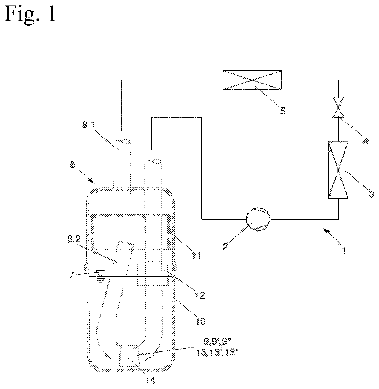
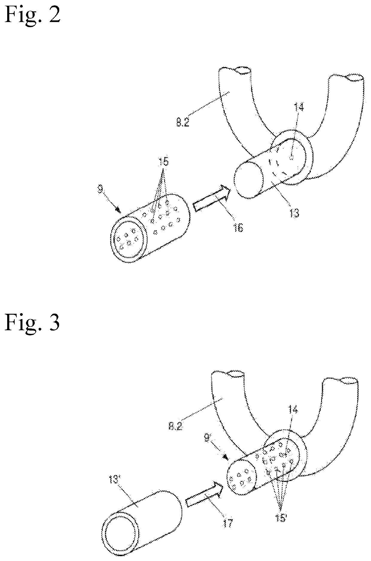
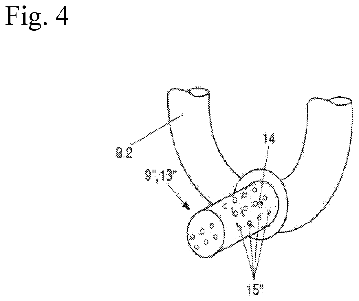
[0036]FIG. 1 illustrates an apparatus for separating and storing liquid refrigerant 6, which includes a boiling element 9, 9′, or 9″ disposed in a refrigerant outflow line 8.2 and is a component of a refrigerant circuit 1 of a compression refrigerator.

[0037]The refrigerant circuit 1 includes a compressor 2 which compresses a gas refrigerant and / or a liquid refrigerant, a heat exchanger 3 whi...


PUM


Abstract

An apparatus for separating and storing liquid refrigerant in a refrigerant circuit including a housing configured as a refrigerant collection container, the housing having a refrigerant outflow line disposed therein. The refrigerant outflow line extending from an inlet opening, which is disposed in a gas refrigerant region and above a level of the liquid refrigerant, via a liquid refrigerant region to the outside, and has a through-opening formed in the liquid refrigerant region. The housing includes a boiling element for liquid refrigerant disposed therein. The boiling element is connected to the refrigerant outflow line in the region of the through-opening, such that a liquid passing through the through-opening from the housing passes through the boiling element by suction of a gas refrigerant.

Description

CROSS-REFERENCE TO RELATED APPLICATIONS[0001]This patent application claims priority to German Patent Application Nos. 10 2015 122 549.2 and 10 2015 122 556.5 filed on Dec. 22, 2015, the disclosures of which are incorporated herein by reference in their entirety.FIELD OF THE INVENTION[0002]Exemplary embodiments of the present invention relate to an apparatus for separating and storing liquid refrigerant in a refrigerant circuit. The apparatus includes a housing defined as a refrigerant collection container, in which case the housing has a refrigerant outflow line disposed therein. The refrigerant outflow line extends from an inlet opening, which is disposed in a gas refrigerant region and above a level of refrigerant, via a liquid refrigerant region to the outside. The refrigerant outflow line has a through-opening formed in the liquid refrigerant region. The housing includes a boiling element for liquid refrigerant disposed therein.BACKGROUND OF THE INVENTION[0003]In various applic...

Claims


Application Information

Patent Timeline
Patent Type & Authority Patents(United States)
IPC IPC(8): F25B43/00
CPCF25B43/006F25B43/003F25B2400/23F25B2500/28F25B43/00F25B2500/12
Inventor SPIES, TONIHEYL, PETERGRAAF, MARCHELM, HARTMUTITTNER, HEINRICHDVORSKY, JIRI
Owner HANON SYST
Why Eureka
Try Eureka