Ventilation system for a garage

Inactive Publication Date: 2006-03-23
THE CHAMBERLAIN GRP INC
View PDF6 Cites 11 Cited by
  • Summary
  • Abstract
  • Description
  • Claims
  • Application Information

AI Technical Summary

Benefits of technology

[0004] One aspect of the invention is to provide a power ventilation system used to eliminate or reduce the fumes and odors created within the garage. A second aspect of this invention is to provide control of the power ventilation system so that this reduction of fumes and odors occurs when it is needed, rather than continuously operating.

Problems solved by technology

They do nothing to eliminate the fumes and odor which usually exists in the garage.

Method used


Image

  • Ventilation system for a garage
  • Ventilation system for a garage
  • Ventilation system for a garage

Examples


Embodiment Construction

[0016] A filler understanding of the invention will be accomplished from the following explanation of a number of embodiments of the present invention.

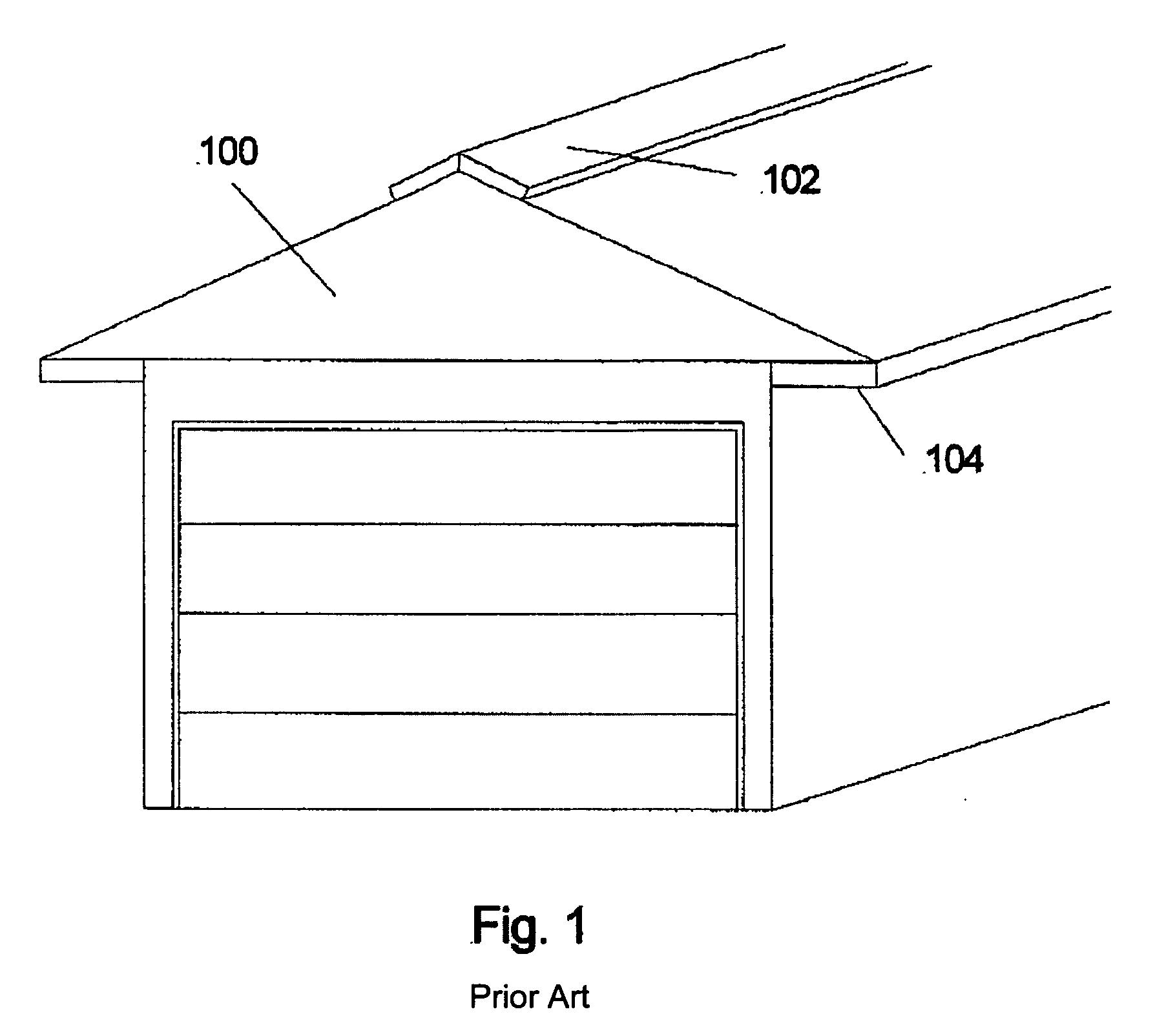
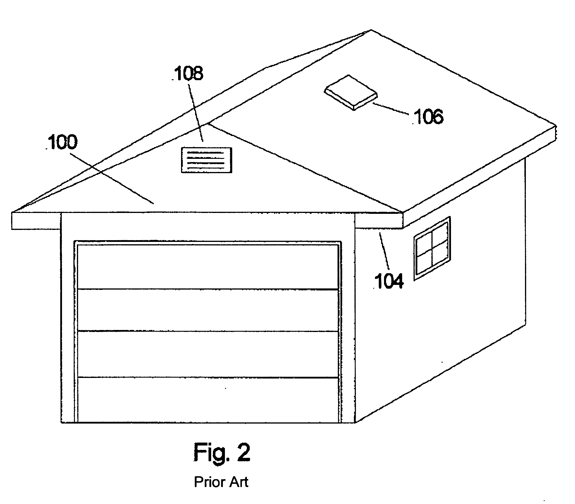
[0017]FIG. 1 is one representation of the present state of the art in ventilation of a garage. The garage 100 has ridge ventilation and soffit ventilation. Air usually flows in through the soffit vents 104 and out through the ridge vents 102. This air flow allows the attic space to remain cooler and drier extending the life of the roof. This system of air flow is also accomplished in the system illustrated in FIG. 2. In FIG. 2, the ridge vent is replaced by either attic vent 106 or face vent 108. Again the usual air flow is from the soffit 104 to the vent.

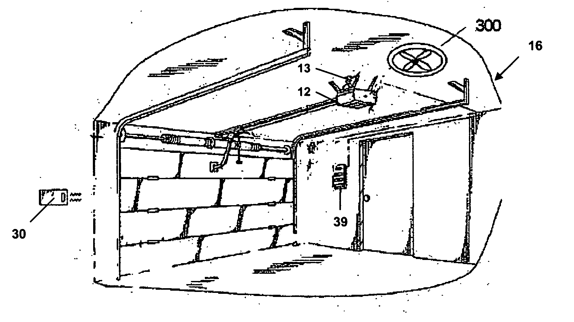
[0018] Current garage ventilation systems do not remove fumes and odor which exist at ground level of the floor. In fact, as garage technology has progressed, the use of drywalled ceilings has increased, increasing the trapping of the fumes within the garage. In FIG. 3, a basic cut...


PUM


Abstract

A power ventilation system comprising an exhaust fan, a power supply, and a control system is provided for ventilation of a garage. The ventilation system may be controlled by a moveable barrier, interfaced to a weather seal of the garage door, or configured to allow power ventilation of the garage when the garage door is closed.

Description

FIELD OF THE INVENTION [0001] This invention relates generally to the concept of ventilation of the garage and more specifically to the operation of a power ventilation system, which is controlled by a movable barrier operator. BACKGROUND OF THE INVENTION [0002] Modern garages are designed with some form of passive ventilation. Methods used in present construction technology include ridge ventilation and roof ventilation usually in combination with soffit ventilation. [0003] These techniques of ventilation are used in order to protect the roof and attic from the environmental hazards of heat and moisture buildup. They do nothing to eliminate the fumes and odor which usually exists in the garage. This invention removes the fumes and odors that are present in the garage. SUMMARY OF THE INVENTION [0004] One aspect of the invention is to provide a power ventilation system used to eliminate or reduce the fumes and odors created within the garage. A second aspect of this invention is to p...

Claims


Application Information

Patent Timeline
IPC IPC(8): H02P1/00
CPCE05Y2900/106F04D25/08E05F15/668F24F7/025F04D25/12
Inventor FITZGIBBON, JAMES J.KARASEK, MARK L.MACK, DAVID T.
Owner THE CHAMBERLAIN GRP INC
Why Eureka
Try Eureka