Projection equipment support system

a technology of supporting system and projection equipment, which is applied in the direction of dismountable cabinets, couplings, instruments, etc., to achieve the effect of facilitating swiveling/positioning of the projector

Inactive Publication Date: 2006-03-23
AR METAL FABTION
View PDF7 Cites 22 Cited by
  • Summary
  • Abstract
  • Description
  • Claims
  • Application Information

AI Technical Summary

Problems solved by technology

The design / arrangement of these support arms is critical as numerous prior art attempts to come up with a general purpose solution to the projector mounting problem have failed.

Method used


Image

  • Projection equipment support system
  • Projection equipment support system
  • Projection equipment support system

Examples


Embodiment Construction

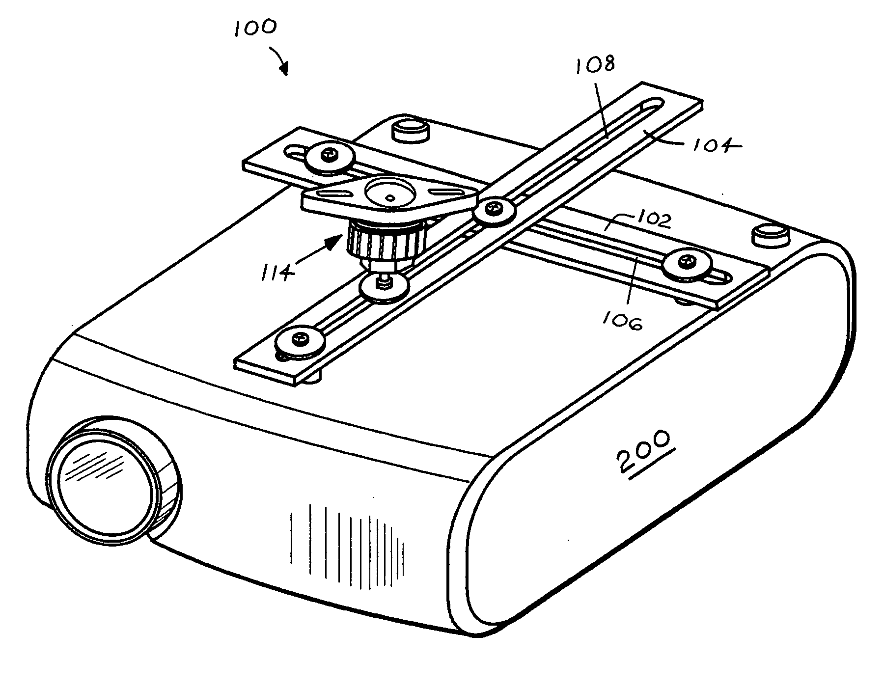
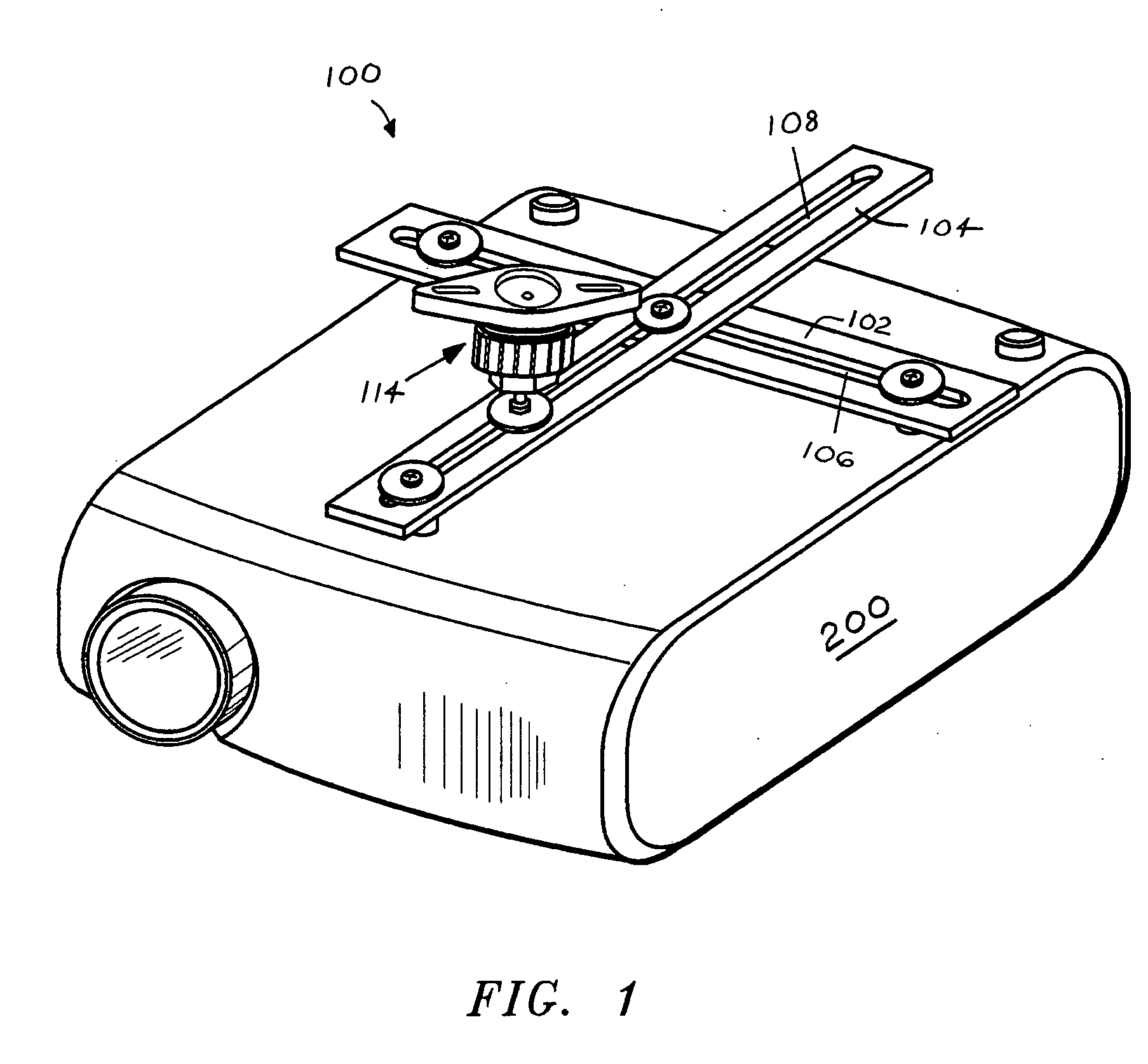
[0032] Turning, now, to the drawings, in which the use of similar reference characters denotes similar elements across the figures, FIG. 3A presents a perspective view of a portion of the invention 100; specifically, it and FIGS. 3B, 3C, and 3D which follow present a view of a sample installation of the invention 100. A second sample installation of the projector support is shown in FIG. 3E.

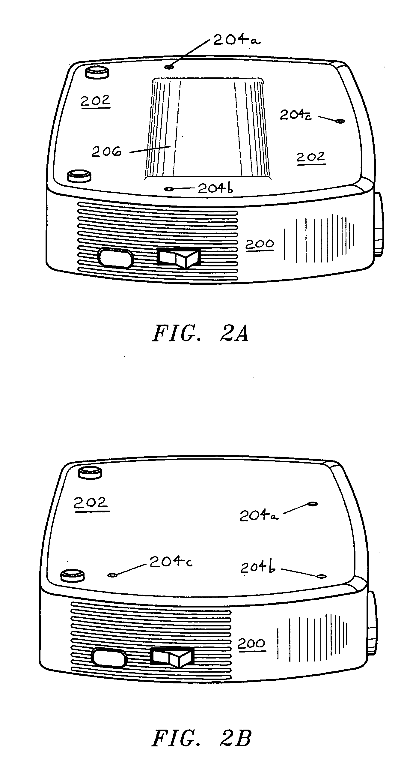
[0033] Returning to FIG. 3A, the projection equipment support system 100 is designed to support the projector 200 through inter-connection with the surface 202 of the projector 200. When the invention 100 (or “projector support 100”) is properly installed and configured, the projector 200 will be maintained at an effectual orientation (relative to a support structure such as the ceiling (the usual case), a wall, or a conference table, podium, or floor) for projection of an image.

[0034] Mounting holes 204 are a characteristic of surface 202 of projector 200, and their presence was emphasized in ...


PUM


Abstract

A novel support system for the mounting / suspension / elevation of a commercial projector is disclosed. The projector support disclosed herein grasps the projector to be mounted at one of its surfaces (typically, the bottom surface) through the use of two support arms. The design / arrangement of these support arms is critical as numerous prior art attempts to come up with a general purpose solution to the projector mounting problem have failed. The support arms are affixed to the projector surface through mounting screws or other equivalent fastening mechanisms. Importantly, the support arms each feature an adjustment slot which runs substantially the entire length of the arms. The presence of the two slotted arms allows for a countless array of scissoring arrangements for the support arms. This is critical because it allows for interconnection with / mounting of the vast majority of commercial projectors (which invariably feature differing constellations of mounting holes). The projector support also employs a primary mount to facilitate swiveling / positioning of the projector so that the unit is effectually oriented for projection.

Description

BACKGROUND OF THE INVENTION Field of the Invention [0001] This invention is directed towards the mounting systems designed to support projection equipment. [0002] Buyer's Remorse: Recognizing the Needfor a Support System After the Purchase of a Projector. [0003] Many purchasers of modern projector systems discover only after removing the projector from its packaging, and placing it in the company conference room, that an effective mounting system for the projector is desperately needed (time is usually short) and not at hand. [0004] Although FIG. 1 depicts a novel projection equipment support system, the details of which will be reviewed shortly hereinbelow, the reader is directed instead initially to FIG. 2A, 2B, 2C, 2D, and 2E. These figures have been included herein for the specific purpose of dramatizing the very real and vexing nature of the problem to which this invention is directed. [0005]FIG. 2A depicts a perspective view of a typical unit of projection equipment 200 (or, p...

Claims


Application Information

Patent Timeline
Patent Type & Authority Applications(United States)
IPC IPC(8): G03B21/22
CPCF16M11/04F16M11/043G03B21/22F16M2200/027F16M11/12
Inventor RIZZO, ANTHONY JOSEPH
Owner AR METAL FABTION
Why Eureka
Try Eureka