Control lever for the angular setting of a stator blade in a turboshaft engine

a stator blade and stator blade technology, which is applied in the direction of machines/engines, stators, liquid fuel engines, etc., can solve the problems of vibration of the control lever, the appearance of splits or cracks in the control lever, and the risk of lever fracture, so as to avoid the appearance of splits or cracks

Active Publication Date: 2006-03-23
SN DETUDE & DE CONSTR DE MOTEURS DAVIATION S N E C M A
View PDF7 Cites 15 Cited by
  • Summary
  • Abstract
  • Description
  • Claims
  • Application Information

AI Technical Summary

Benefits of technology

[0008] The purpose of the present invention is to avoid the appearance of splits or cracks in a

Problems solved by technology

During the functioning of the turboshaft engine, these control levers are subjected to vibrations due, in particular, to the passages of the rotor blades in front of the stator blades, the frequencies of these vibrations varying with the speed of rotation of the rotor.
It has been observed that these frequencies could coincide with a vibratory mode of said levers, and that the resultant stresses undergone by the levers could cause the appearance of splits or cracks in these levers, particularly in the zone

Method used


Image

  • Control lever for the angular setting of a stator blade in a turboshaft engine
  • Control lever for the angular setting of a stator blade in a turboshaft engine

Examples


Embodiment Construction

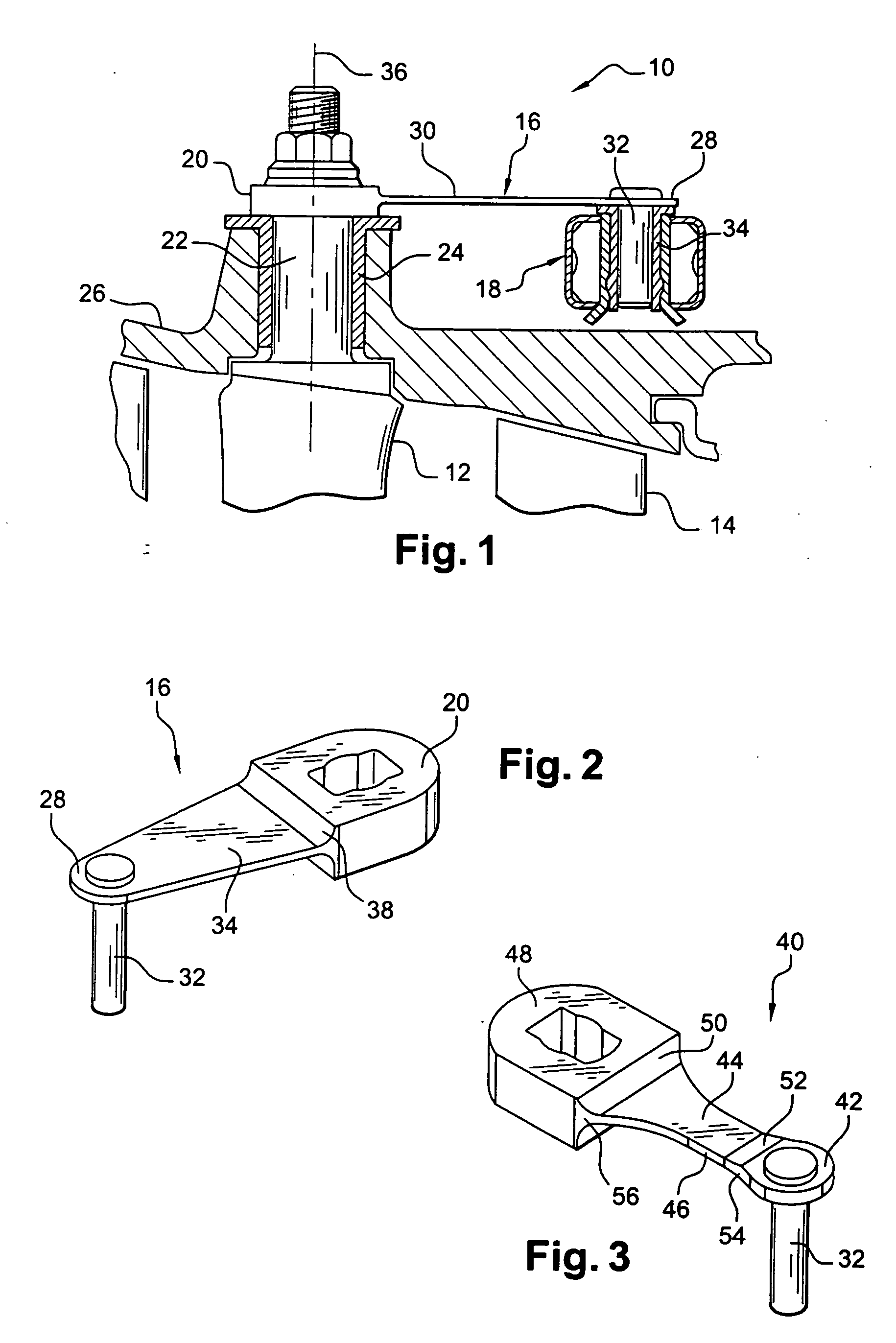
[0024]FIG. 1 shows a part of a high-pressure compressor 10 of a turboshaft engine, in which each stage of the compressor comprises a row of guide vane blades 12 fitted on the stator and a row of blades 14 carried by the rotor.

[0025] The blades 12 of the stator are downstream guide vane blades whose orientation or angular setting is adjustable using control levers 16 driven by a control ring 18 actuated by drive means (not shown) of the jack or electric motor type.

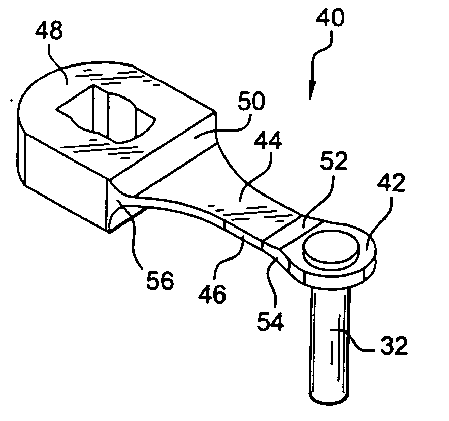
[0026] Each control lever 16 comprises a first end 20 fixed to a radial pivot 22 of a blade 12, guided in rotation in a bearing 24, mounted in a radial shaft of an external casing 26, a second end 28 and a flat intermediate part 30 connecting the ends 20 and 28.

[0027] The second end 28 of the control lever 16 carries a cylindrical pin 32 which is crimped on this end 28 and is guided in rotation in a cylindrical socket 34 of the control ring 18.

[0028] An angular displacement of the control ring 18 about the axis of the c...


PUM

PropertyMeasurementUnit
Thicknessaaaaaaaaaa
Shapeaaaaaaaaaa
Radiusaaaaaaaaaa

Abstract

Control lever for the angular setting of a stator blade, comprising a first end intended to be fitted in a fixed manner on a blade pivot, a second end comprising a cylindrical pin for fitting on a control ring, and a flat intermediate part connecting the first and second ends having shapes and dimensions determined in order to increase the natural frequencies of the lever in flexion and in torsion above the vibratory frequencies of the turboshaft engine upstream of the lever and in order to retain the stiffness of the lever.

Description

[0001] The present invention relates to a control lever for the angular setting of a stator blade in a turboshaft engine and a turboshaft engine compressor comprising a plurality of variable setting angle stator blades equipped with these control levers. BACKGROUND OF THE INVENTION [0002] The adjustment of the angular setting of the stator blades in a turboshaft engine such as a turbojet is intended to optimize the efficiency of this turboshaft engine and to reduce its consumption of fuel in the different flight configurations. [0003] This adjustment is carried out by means of a lever which comprises a first end fitted in a fixed manner on a pivot of the blade in order to drive it in rotation about its longitudinal axis, a second end comprising a cylindrical pin for fitting on a control ring which surrounds the stator of the turboshaft engine externally and which is movable in rotation about the longitudinal axis of the stator by a drive means such as a jack or an electric motor, an...

Claims


Application Information

Patent Timeline
IPC IPC(8): F04D29/44F01D17/16F04D29/56
CPCF01D17/162F04D29/563F04D29/668F05D2300/133F05D2250/712
Inventor BOURGOIN, SEBASTIENFOLLONIER, CHRISTOPHELEJARS, CLAUDE ROBERT LOUISGABRIEL TOURNE, CHRISTOPHE YVONPONTOIZEAU, BRUCE DANIEL JEANTRICONNET, NICOLAS CHRISTIAN
Owner SN DETUDE & DE CONSTR DE MOTEURS DAVIATION S N E C M A
Why Eureka
Try Eureka