Hot-melt conjugate fiber
- Summary
- Abstract
- Description
- Claims
- Application Information
AI Technical Summary
Benefits of technology
Problems solved by technology
Method used
Image
Examples
Example
EXAMPLES 1 AND 2 AND COMPARATIVE EXAMPLES 1 TO 3
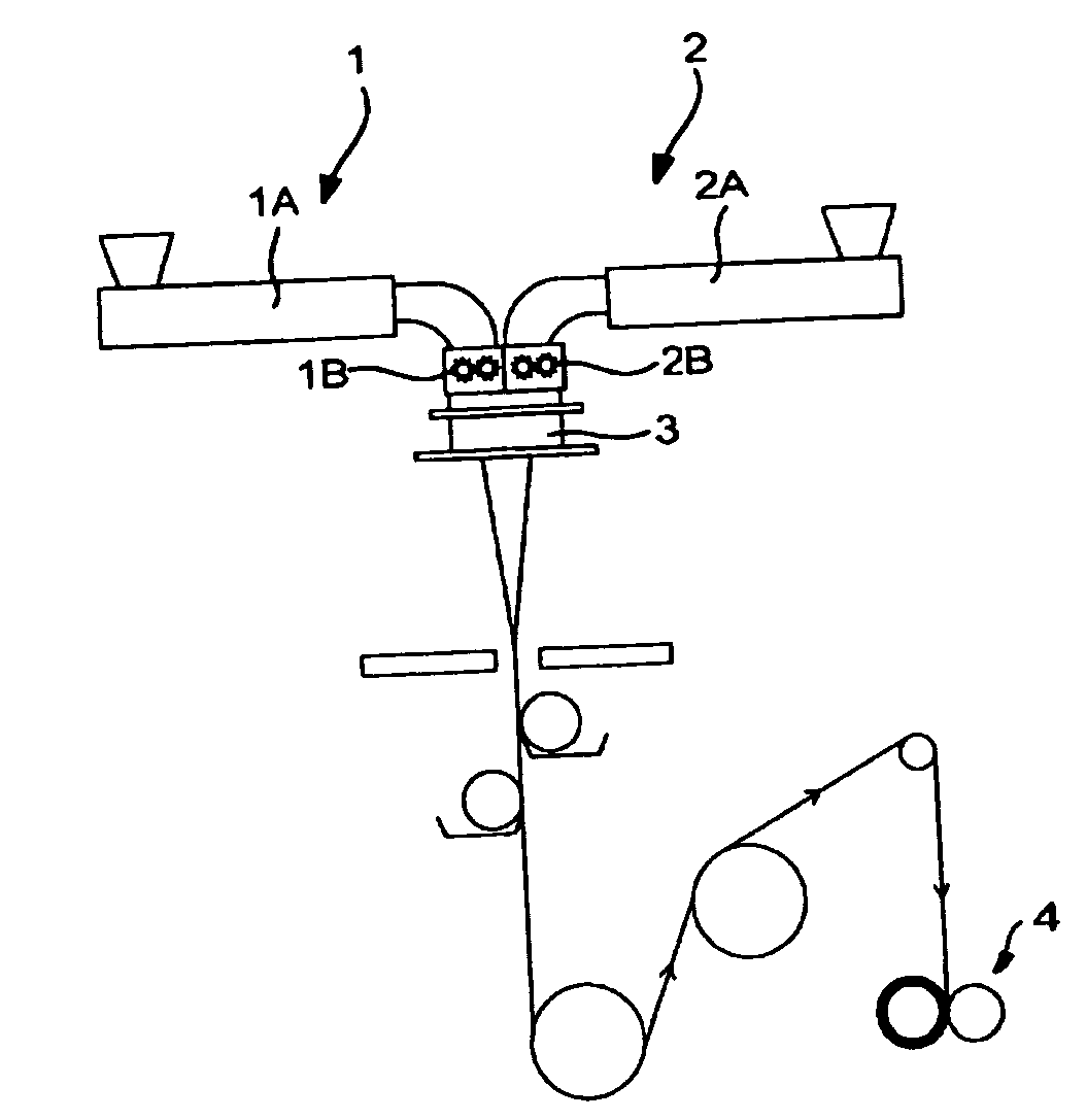
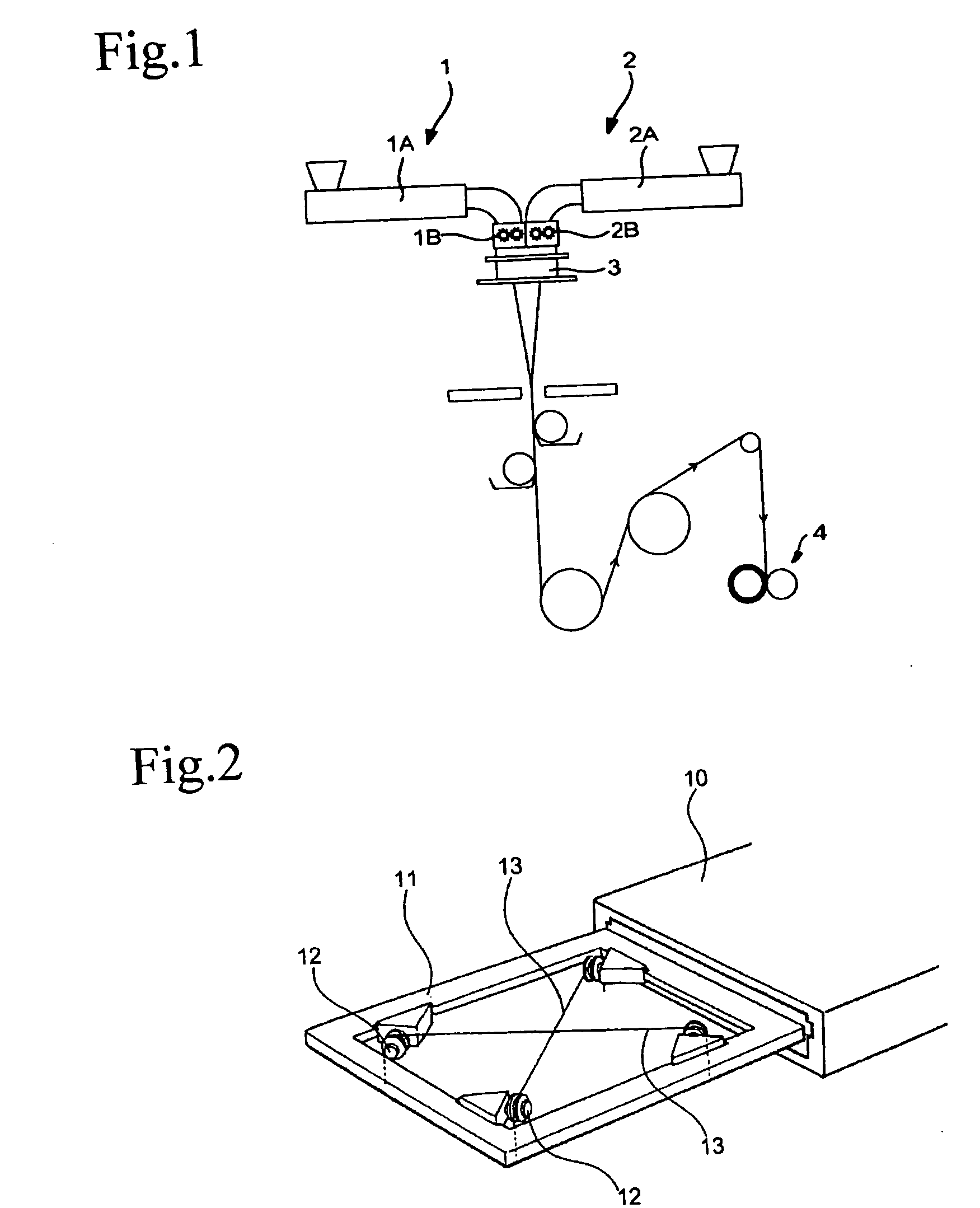
[0039] Concentric sheath-core conjugate fibers were prepared by high-speed melt spinning under the conditions shown in Table 1 below. The resulting conjugate fibers were analyzed for orientation index and heat shrinkage in accordance with the methods described above. Furthermore, the melting point of the resins and the fusion bond strength of the fibers were measured in accordance with the methods described below. The results obtained are shown in Table 1.
Measurement of Melting Point of Resin
[0040] A sample weighing 2 g, prepared by finely cutting the fiber, was analyzed by thermometry with a differential scanning calorimeter, DSC-50 from Shimadzu Corp., at a rate of temperature rise of 10° C. / min. The melting peak temperature was taken as the melting point of the resin.
Measurement of Fusion Bond Strength
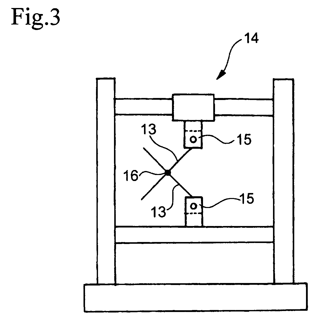
[0041] The device for forming a fusion bond shown in FIG. 2 was used. The device has an oven 10 and a frame 11 for straining f...
Example
EXAMPLES 3 AND 4 AND COMPARATIVE EXAMPLES 4 TO 6
[0042] Each of the conjugate fibers obtained in Examples 1 and 2 and Comparative Examples 1 to 3 was cut into staple fiber of 51 mm length, and the staple fiber was two-dimensionally crimped by mechanical crimping. The crimped staple fiber was carded into a web. Hot air at 135° C. was blown to the carded web at a velocity of 0.5 m / sec for 30 seconds by a through-air process to obtain an air-through nonwoven fabric in which the individual fibers were fusion bonded at their intersections. While, in the above-described fusion bond strength measurement, the fusion bond was formed at the ambient temperature, the air-through nonwoven fabric was obtained by blowing hot air by means of a fan. It should be noted, therefore, that the heating conditions are not quite the same even with the temperature and time conditions being equal.
[0043] The resulting nonwoven fabrics were evaluated for bulkiness and measured for strength at break in accordan...
Example
EXAMPLE 5 AND COMPARATIVE EXAMPLES 7 AND 8
[0047] Concentric sheath-core conjugated fibers were obtained by melt spinning under the conditions shown in Table 3. The resulting conjugated fibers were examined for orientation index and heat shrinkage, and the melting point of the resins and the fusion bond strength of the fibers were measured in the same manner as described above. The results obtained are shown in Table 3. TABLE 3Comparative ExampleExample 5781st Resin ComponentPPPPPP2nd Resin ComponentHDPEHDPEHDPESpinneret Temperature (° C.)250250250Spinning Speed (m / min)1360760390Draw Ratio024Orientation Index1st Resin606895(%)Component2nd Resin165064ComponentHeat Shrinkage (%)*−0.334.881.09Melting Point (° C.)1st Resin160160165Component2nd Resin127129130ComponentFusion Bond140° C. / 30 s32.938.237.0Strength (mN / tex)145° C. / 20 s37.830.132.6145° C. / 30 s33.837.033.5145° C. / 40 s33.525.339.7
*Measured at a temperature higher than the melting point of the second resin component by 10° C.
PUM
| Property | Measurement | Unit |
|---|---|---|
| Temperature | aaaaa | aaaaa |
| Fraction | aaaaa | aaaaa |
| Fraction | aaaaa | aaaaa |
Abstract
Description
Claims
Application Information
 - R&D
- Intellectual Property
- Life Sciences
- Materials
- Tech Scout
- Unparalleled Data Quality
- Higher Quality Content
- 60% Fewer Hallucinations
Browse by: Latest US Patents, China's latest patents, Technical Efficacy Thesaurus, Application Domain, Technology Topic, Popular Technical Reports.
© 2025 PatSnap. All rights reserved.Legal|Privacy policy|Modern Slavery Act Transparency Statement|Sitemap|About US| Contact US: help@patsnap.com


