Interspinous process implant including a binder and method of implantation

a technology of interspinous process and binder, which is applied in the field of interspinous process implants, can solve the problems of segment instability, disk pain during flexion and facet pain, and compromise of the structure of the intervertebral disk

Inactive Publication Date: 2006-03-23
BEA SYST INC +1
View PDF98 Cites 420 Cited by
  • Summary
  • Abstract
  • Description
  • Claims
  • Application Information

AI Technical Summary

Problems solved by technology

In the spine, the structure of the intervertebral disks can be compromised, in part as the structure of the annulus fibrosus of the intervertebral disk weakens due to degenerative effects.
Spondylosis in the thoracic region of the spine can cause disk pain during flexion and facet pain during hyperextension.
Over time, loss of disk height can result in a degenerative cascade with deterioration of all components of the motion segment resulting in segment instability and ultimately in spinal stenosis (including, but not limited to, central canal and lateral stenosis).
Spinal stenosis results in a reduction in foraminal area (i.e., the available space for the passage of nerves and blood vessels) which compresses the nerve roots and causes radicular pain.
Extension and ipsilateral rotation further reduces the foraminal area and contributes to pain, nerve root compression and neural injury.
During the process of deterioration, disks can become herniated and/or become internally torn and chronically painful.
When symptoms seem to emanate from both anterior (disk) and posterior (facets and foramen) structures, patients cannot tolerate positions of extension or flexion.
Supplemental devices have the disadvantage that they generally require extensive surgical procedures in addition to the extensive procedure surrounding the primary fusion implant.
Such extensi

Method used


Image

  • Interspinous process implant including a binder and method of implantation
  • Interspinous process implant including a binder and method of implantation
  • Interspinous process implant including a binder and method of implantation

Examples


Embodiment Construction

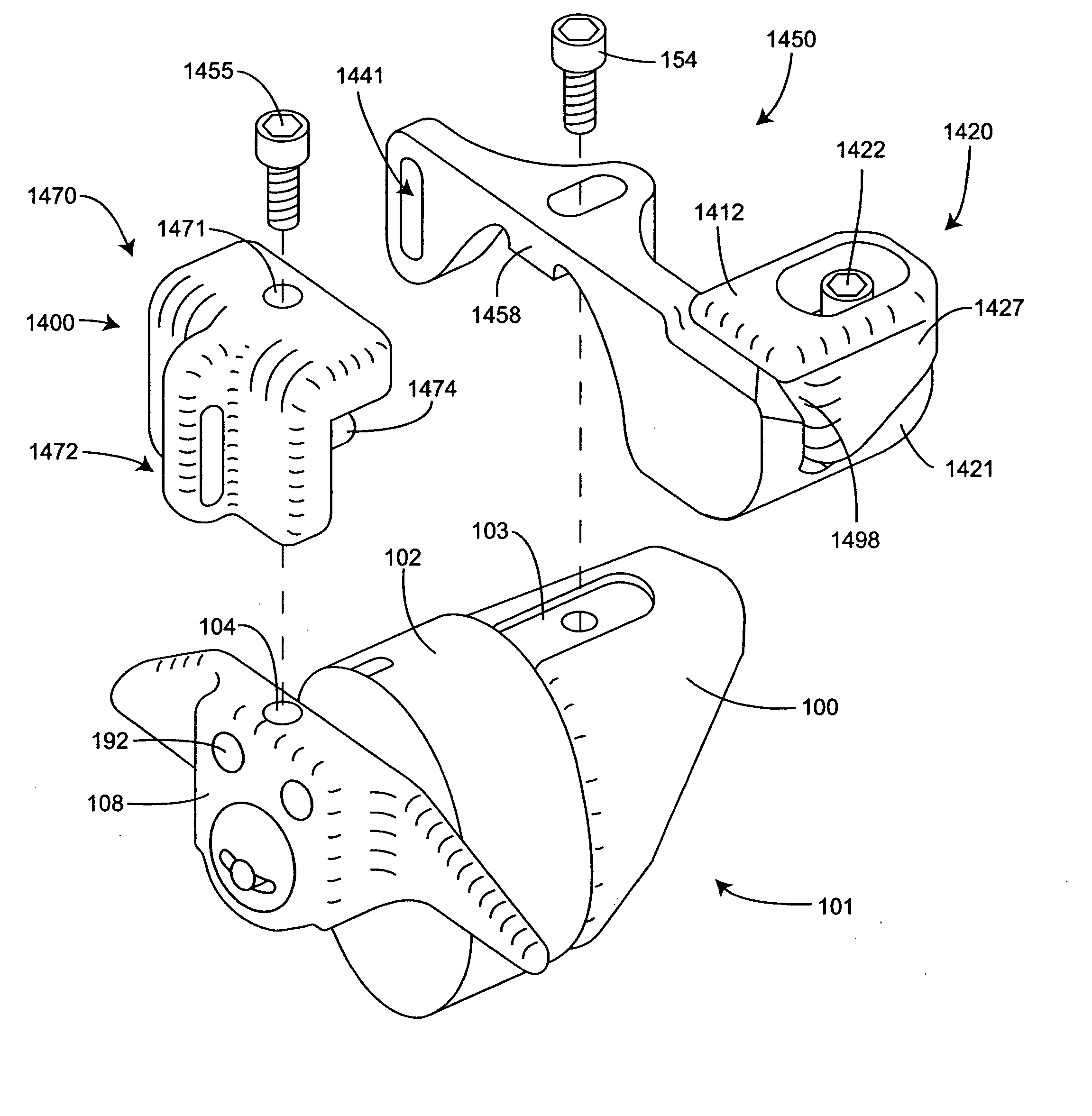
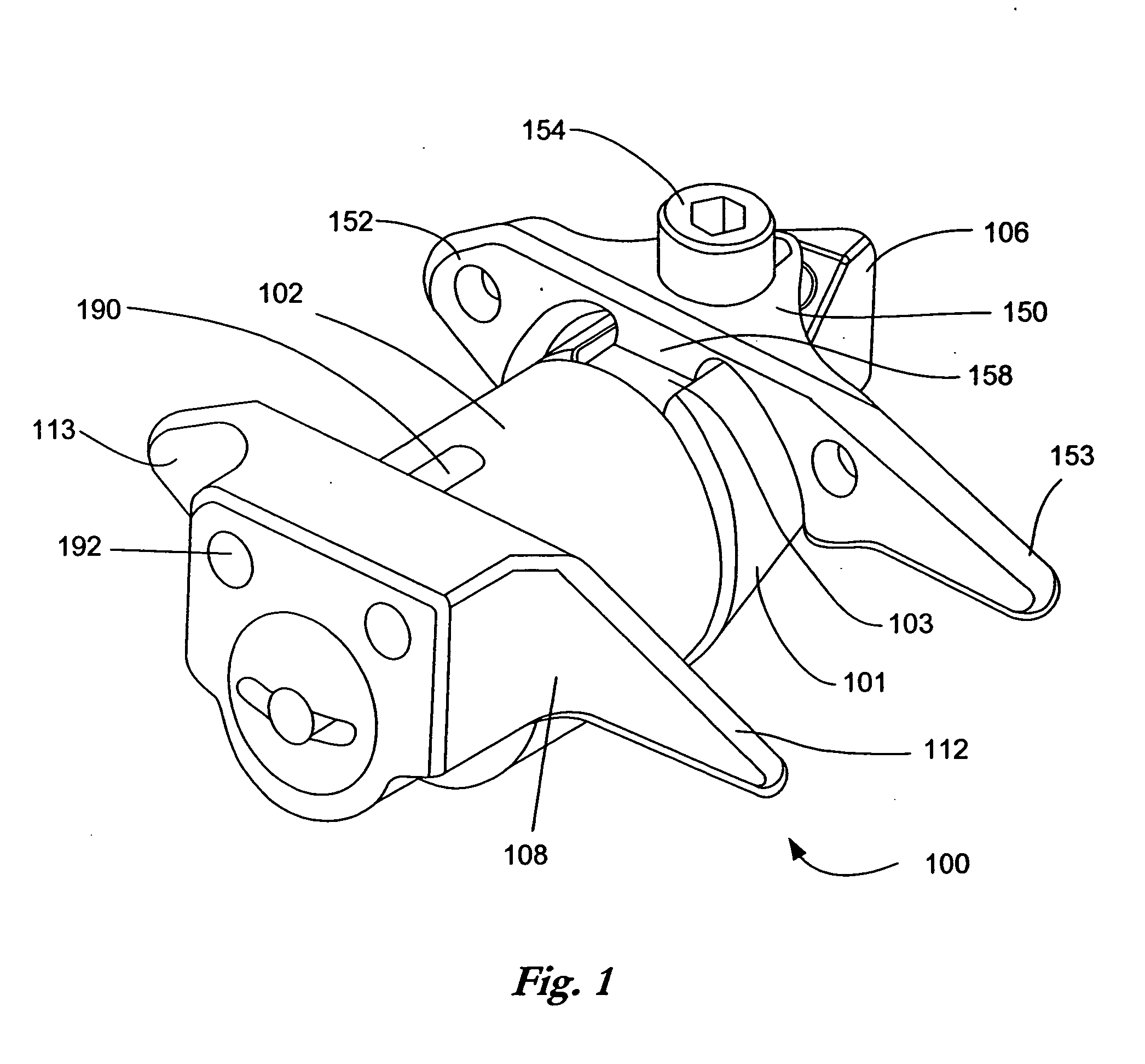
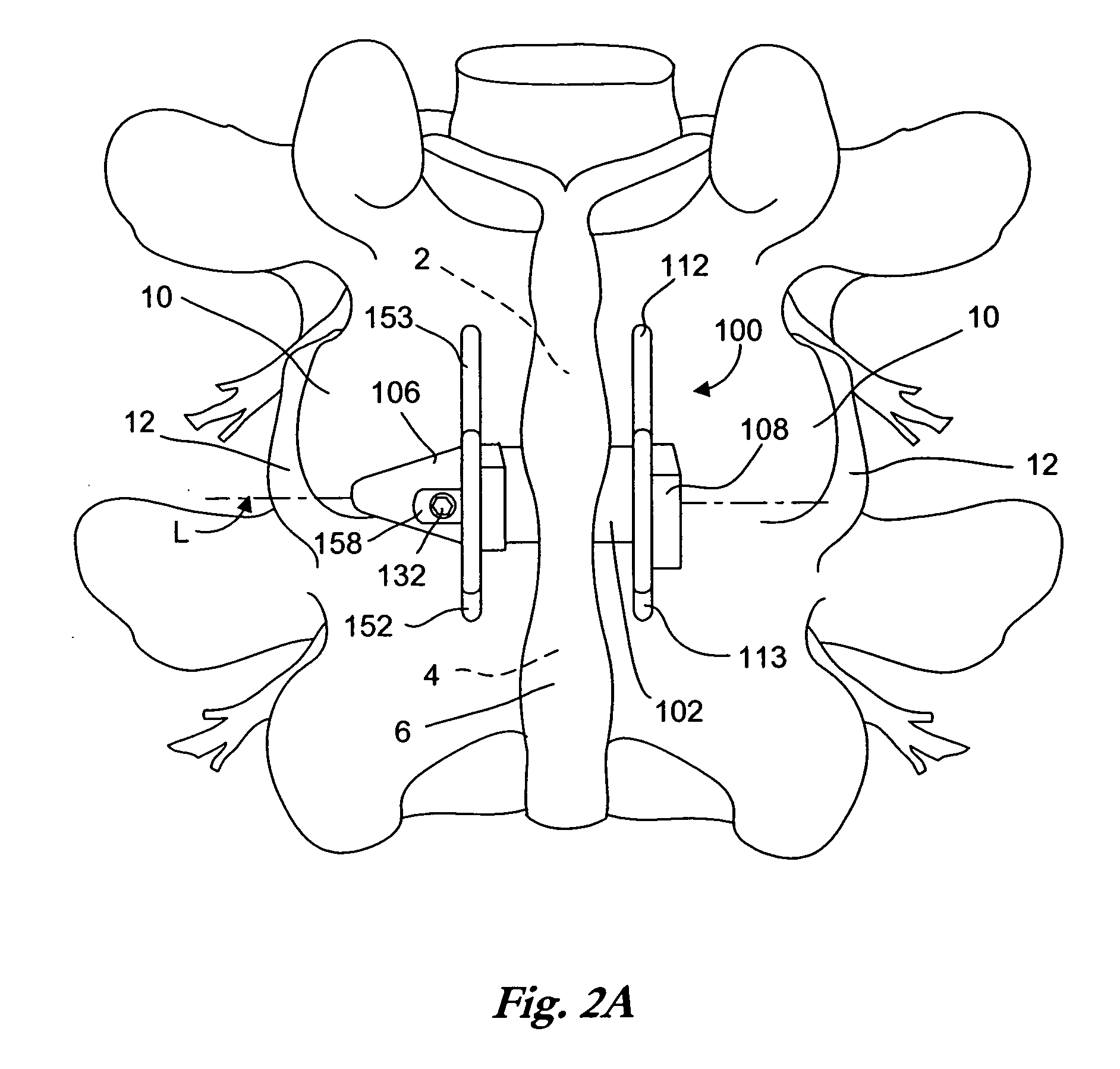
[0056]FIG. 1 is a perspective view of an implant as described in U.S. Pat. No. 6,695,842 to Zucherman, et al. and U.S. Pat. No. 6,712,819 to Zucherman et al., both incorporated herein by reference. The implant 100 has a main body 101. The main body 101 includes a spacer 102, a first wing 108, a lead-in tissue expander 106 (also referred to herein as a distraction guide) and an alignment track 103. The main body 101 is inserted between adjacent spinous processes. Preferably, the main body 101 remains (where desired) in place without attachment to the bone or ligaments.

[0057] The distraction guide 106 includes a tip from which the distraction guide 106 expands, the tip having a diameter sufficiently small such that the tip can pierce an opening in an interspinous ligament and / or can be inserted into a small initial dilated opening. The diameter and / or cross-sectional area of the distraction guide 106 then gradually increases until it is substantially similar to the diameter of the ma...


PUM


Abstract

Systems in accordance with embodiments of the present invention can include an implant comprising a spacer for defining a minimum space between adjacent spinous processes, a distraction guide for piercing and distracting an interspinous ligament during implantation, and a binder for limiting or preventing flexion motion of the targeted motion segment. The binder can be secured to a brace associated with the implant during implantation by a capture device. In one embodiment, the capture device includes a fixed piece extending from the brace and a slidable piece associated with the fixed piece. A fastener can be rotated to pinch the binder between the slidable piece and a wall of the brace, securing the binder. A physician need not know the length of the binder prior to implantation, reducing the time required to perform a procedure.

Description

CLAIM OF PRIORITY [0001] This application claims priority to U.S. Provisional Patent Application No. 60 / 612,465 entitled “Interspinous Process Implant Including a Binder and Method of Implantation,” by Zuchernan et al., filed Sep. 23, 2004, incorporated herein by reference. CROSS-REFERENCE TO RELATED APPLICATIONS [0002] This U.S. Provisional Patent Application incorporates by reference all of the following co-pending applications and issued patents: [0003] U.S. patent application, entitled “Distractible Interspinous Process Implant and Method of Implantation,” filed May 20, 2004, Ser. No. 10 / 850,267; [0004] U.S. Pat. No. 6,419,676, entitled “Spine Distraction Implant and Method,” issued Jul. 16, 2002 to Zucherman, et al.; [0005] U.S. Pat. No. 6,451,019, entitled “Supplemental Spine Fixation Device and Method,” issued Sep. 17, 2002 to Zucherman, et al.; [0006] U.S. Pat. No. 6,582,433, entitled “Spine Fixation Device and Method,” issued Jun. 24, 2003 to Yun; [0007] U.S. Pat. No. 6,652...

Claims


Application Information

Patent Timeline
IPC IPC(8): A61F2/44
CPCA61B17/7068A61F2/44
Inventor ZUCHERMAN, JAMES F.HSU, KEN Y.KLYCE, HENRYWINSLOW, CHARLES J.FLYNN, JOHN J.MITCHELL, STEVE T.YERBY, SCOTT A.MARKWART, JOHN A.
Owner BEA SYST INC
Why Eureka
Try Eureka