
Reciprocationg saw and guard rail assembly therefor

a technology of reciprocating saws and guard rails, which is applied in the direction of metal sawing devices, metal sawing accessories, manufacturing tools, etc., can solve the problems of limiting the angular range of bevel cuts that can be achieved, user's sight to the blade may be obstructed by the guard rail, etc., to prevent the projecting of dust, obscuring the view of the operator, and facilitating the effect of forward projection

Inactive Publication Date: 2006-03-30
BLACK & DECKER INC
View PDF34 Cites 15 Cited by
  • Summary
  • Abstract
  • Description
  • Claims
  • Application Information

AI Technical Summary

Benefits of technology

[0008] By providing a guard means mounted on the base plate of the tool, this provides the advantage that when the tool is tilted for bevel cutting, the body of the tool is prevented from coming into contact with the guard means, thereby providing an increased range of bevel cutting angles. A further advantage is provided in that a flush cut blade can extend forwardly almost to the front of the base plate, but behind the guard means. This allows the tool to cut a portion of a workpiece even when the body of the tool is prevented from passing over that portion of the workpiece. Moreover, the advantage is provided that the guard means prevents objects other than the workpiece from coming into contact with the working member of the tool.
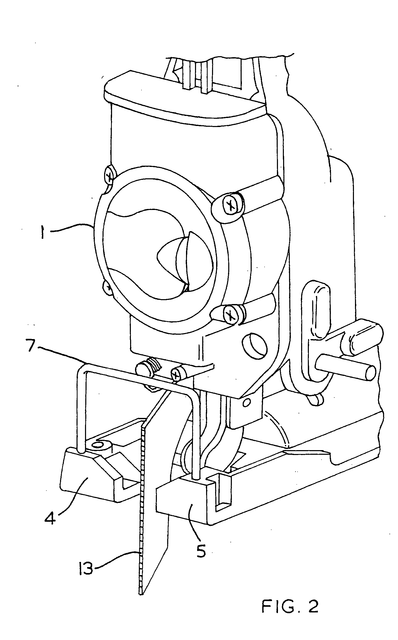
[0009] In a preferred embodiment, the guard means is adapted to be mounted to at least one groove formed in said base plate. This provides the advantage that the guard means reinforces the shoe of the jigsaw. In a preferred embodiment, at least one said groove is formed in the underside of said base plate. At least one said groove may extend from the underside of said base plate along a forward edge of the base plate. This provides the advantage that the forward edge of the guard rail protects the front of the shoe. The assembly may comprise first and second grooves formed respectively on either side of said aperture. At least one groove may comprise a slot for resiliently receiving a portion of said guard means.
[0011] The assembly may further comprise a dust guard adapted to engage said guard means. This provides the advantage that dust is prevented from projecting in front of the tool and obscuring the view of the operator.
[0012] The guard means may be removable from said base plate. This provides the advantage that flush cut blades of even greater forward projection can be fitted to the tool.

Problems solved by technology

A problem arises with guard rails of this type when the jigsaw is being used for bevel cutting.
This effectively limits the angular range of bevel cuts that can be achieved.
The problem also arises that the user's line of sight to the blade may be obstructed by the guard rail.

Method used


Image

  • Reciprocationg saw and guard rail assembly therefor
  • Reciprocationg saw and guard rail assembly therefor
  • Reciprocationg saw and guard rail assembly therefor

Examples


Embodiment Construction

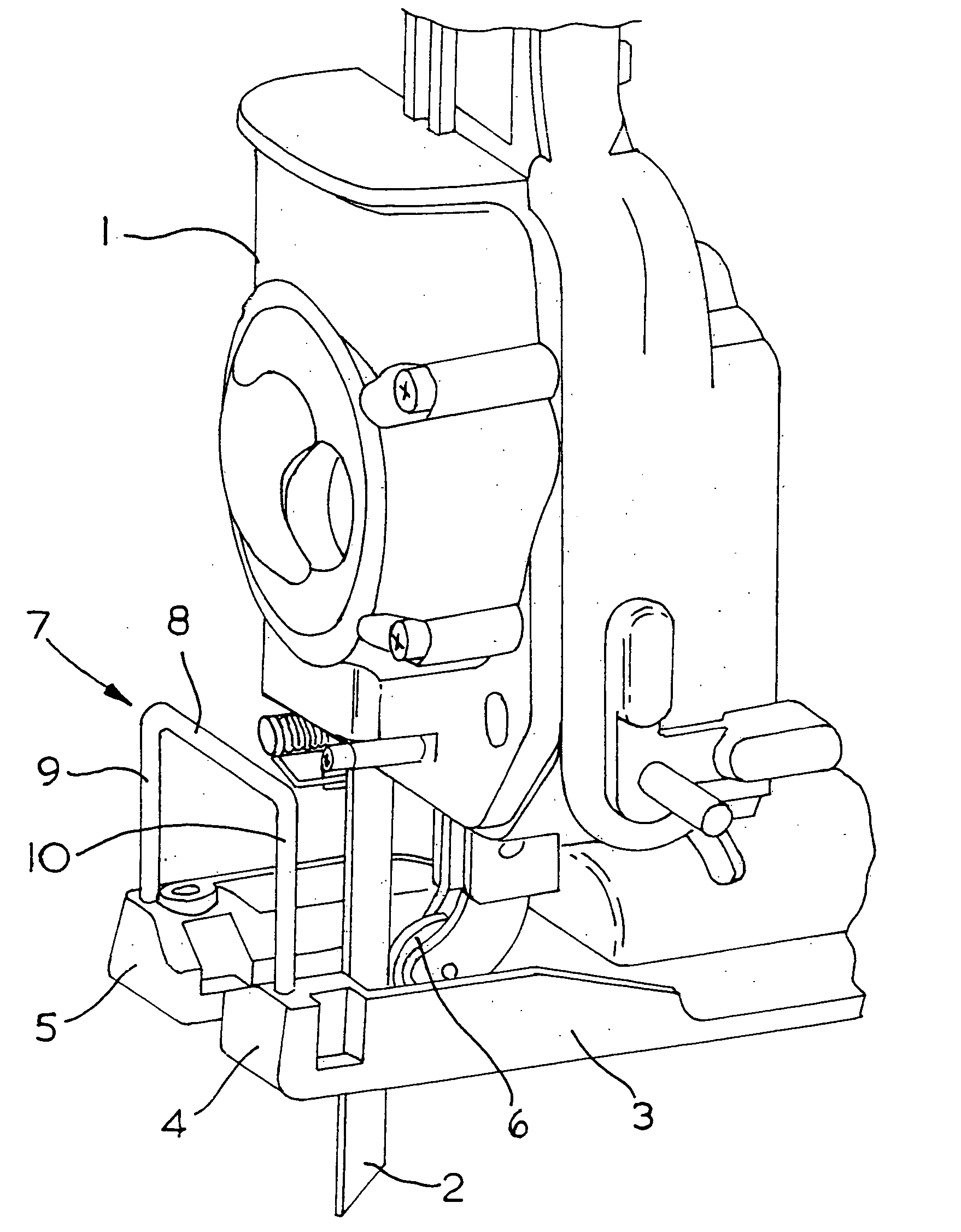
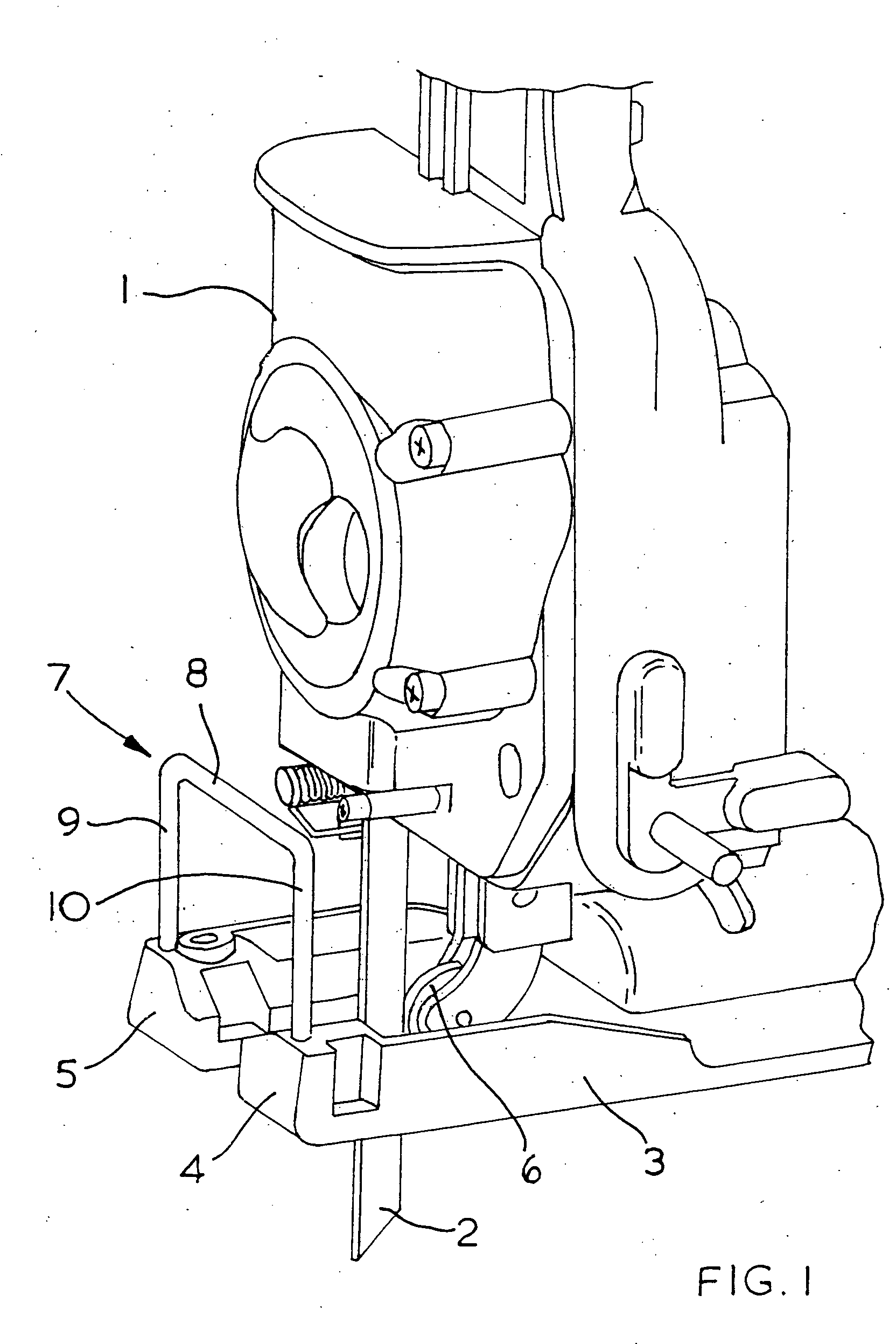
[0028] Referring to FIG. 1, a jigsaw comprises a body 1 (only the front of which is shown in FIG. 1) housing a motor (not shown) and a drive mechanism (not shown) to convert the rotary output of the motor into reciprocal motion to drive a blade 2. The body 1 is mounted on a shoe 3 which is formed from a metal cast and has two forwardly projecting arms 4, 5. The blade 2 is supported by a blade support roller 6 which provides a reaction force for the blade along the longitudinal axis of the jigsaw during cutting. A guard rail, shown generally by 7, comprises a horizontal bar 8 supported by upright portions 9, 10 which respectively engage arms 4, 5. The guard rail 7 is formed from a single metal bar bent into shape.

[0029] During operation of the jigsaw, the underside of the shoe 3 is placed on the workpiece to be cut. The teeth (not shown) of the blade 2 are angled such that on the upstroke of the blade the workpiece is cut, and on the downstroke of the blade any swarf that is produce...


PUM


Abstract

A jigsaw comprises a body housing a motor and a drive mechanism to convert the rotary output of the motor into reciprocal motion of the drive the blade. The body 1 is mounted on a shoe which has two forward projecting arms. A guard rail is mounted on the shoe at the front end of the arms and comprises a horizontal bar supported by upright portions which respectively engage the arms. The guard rail is formed from a single metal bar.

Description

FIELD OF THE INVENTION [0001] The present invention relates to a guard rail assembly for a working member of a reciprocating tool and relates particularly, but not exclusively, to a guard rail assembly for the blade of a reciprocating jig saw. BACKGROUND OF THE INVENTION [0002] Jigsaws are power tools which comprise a reciprocating saw blade for cutting a workpiece of wood or other material. Jigsaws generally comprise a body housing an electric motor and a drive mechanism to convert the rotary motion of an output shaft of the motor into reciprocal motion of the blade. Jigsaws are also provided with a supporting shoe in the form of a flat surface which rests on the workpiece and provides a reaction surface for cutting. The jigsaw body may also be able to pivot laterally about the longitudinal axis of the jigsaw to enable bevel cutting of the workpiece. [0003] A further feature of many jigsaws is a guard rail mounted on the underside of the body of the jigsaw which extends forwardly o...

Claims


Application Information

Patent Timeline
IPC IPC(8): B23D49/16
CPCB23D49/162
Inventor WILSON, MIKEWALMSLEY, NEIL
Owner BLACK & DECKER INC
Learn More