Leg assembly for paper pallet

Inactive Publication Date: 2006-03-30
CHEN FU MEI
View PDF14 Cites 22 Cited by
  • Summary
  • Abstract
  • Description
  • Claims
  • Application Information

AI Technical Summary

Benefits of technology

[0007] An objective of the present invention is to provide

Problems solved by technology

However, the forks of the forklift could not be inserted into the paper pallet 90 along a transverse direction, causing limitation to operation of the forklift.
To provide openings in the transver

Method used


Image

  • Leg assembly for paper pallet
  • Leg assembly for paper pallet
  • Leg assembly for paper pallet

Examples


Embodiment Construction

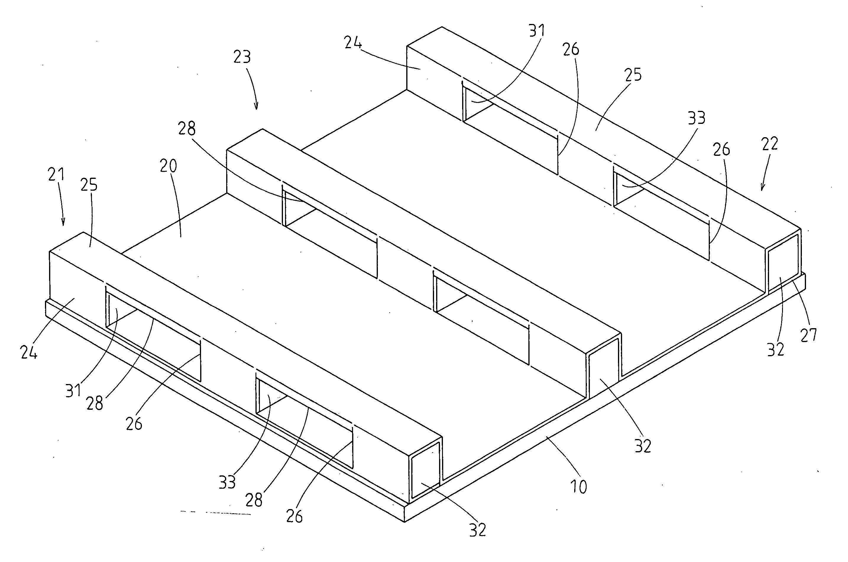
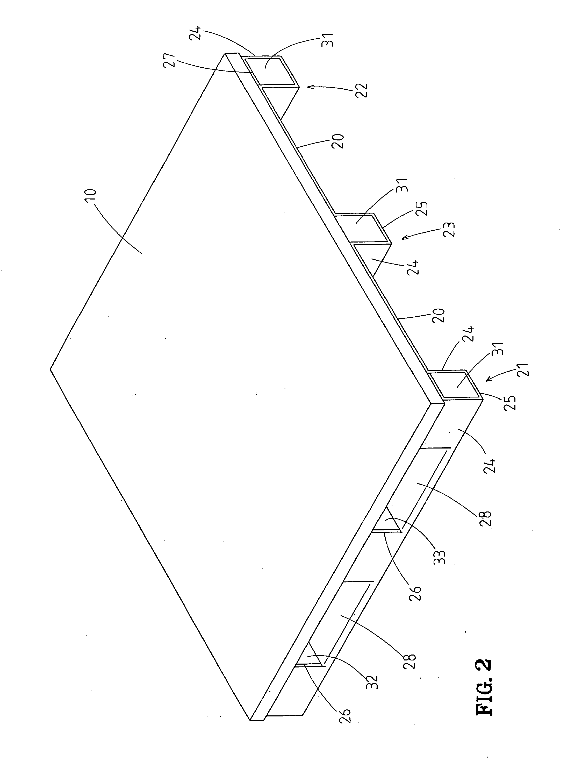
[0025]FIG. 2 illustrates an embodiment of a pallet in accordance with the present invention. The pallet comprises a top plate 10 and a leg assembly fixed below the top plate 10. The top plate 10 is substantially square or rectangular and may be formed by bonding a plurality of sheets of corrugated paper or thick paper. Cargo or the like is placed on a top side of the top plate 10. The leg assembly is also made of corrugated paper or thick paper. It is, however, noted that the top plate 10 and the leg assembly of the pallet can be made of any other suitable material.

[0026] Referring to FIGS. 2 through 4, the leg assembly comprises a bottom plate 20 and a plurality of supporting blocks 31, 32, and 33. The bottom plate 50 defines a plurality of compartments (not labeled) for receiving the supporting blocks 31, 32, and 33. In the illustrated embodiment, the bottom plate 20 comprises three receiving sections 21, 22, and 23 spaced from one another by a longitudinal space (not labeled). E...


PUM


Abstract

A pallet includes a top plate and a leg assembly fixed below the top plate. The leg assembly includes a bottom plate fixed below the top plate. The bottom plate includes three receiving sections spaced from one another. Each receiving section includes two longitudinal sides and a bottom side. Three supporting blocks are mounted in each receiving section and spaced from one another. Each longitudinal side of each receiving section includes two transverse openings. Each transverse opening on each receiving section is located between two of the supporting blocks adjacent to each other.

Description

CROSS REFERENCE TO RELATED APPLICATION [0001] This is a continuation-in-part application of U.S. patent application Ser. No. 10 / 950,203 filed Sep. 24, 2004.BACKGROUND OF THE INVENTION [0002] 1. Field of the Invention [0003] The present invention relates to a pallet. In particular, the present invention relates to a paper pallet. [0004] 2. Description of the Related Art [0005] Paper pallets are more widely used than conventional wooden pallets and metal pallets, as the paper pallets are light, inexpensive, and recyclable. FIG. 1 of the drawings illustrates a typical paper pallet 90 comprising a top plate 91 and a plurality of legs 92 supporting the top plate 91. The top plate 91 is comprised of a plurality of sheets that are made of corrugated paper or thick paper and that are bonded together to improve the strength of the paper pallet 90. [0006] Two forks of a forklift are inserted into the spaces between the legs 92 along a longitudinal direction for lifting the paper pallet 90. Ho...

Claims


Application Information

Patent Timeline
IPC IPC(8): B65D19/00
CPCB65D19/0026B65D2519/00019B65D2519/00054B65D2519/00089B65D2519/00124B65D2519/00562B65D2519/00318B65D2519/00333B65D2519/00373B65D2519/00402B65D2519/00557B65D2519/00293
Inventor CHEN, FU-MEI
Owner CHEN FU MEI
Why Eureka
Try Eureka