Direct flow filter with sealing mechanism

a filter and flow filter technology, applied in the field of direct flow filter, can solve the problems of increasing restriction, variation in sealing thickness, manufacturing challenges, etc., and achieve the effect of simple and effective manner

Inactive Publication Date: 2006-03-30
FLEETGUARD INC
View PDF13 Cites 46 Cited by
  • Summary
  • Abstract
  • Description
  • Claims
  • Application Information

AI Technical Summary

Benefits of technology

[0007] The present invention addresses and solves the above noted

Problems solved by technology

This presents manufacturing challenges because the hot melt must be applied to both the top and bottom surfaces of the media during pleating.
A drawback of the noted hot melt sealing is variation in thickness, which is due to many variables.
The result is a leading and/or trailing edge which varies in thickness and can increase restriction, which is undesirable in a filter.
A further disadvantage of hot melt sealing is that the edges of the filter media are exposed to damage, including leading edges from incoming debris, or other physical

Method used


Image

  • Direct flow filter with sealing mechanism
  • Direct flow filter with sealing mechanism
  • Direct flow filter with sealing mechanism

Examples


Embodiment Construction

Prior Art

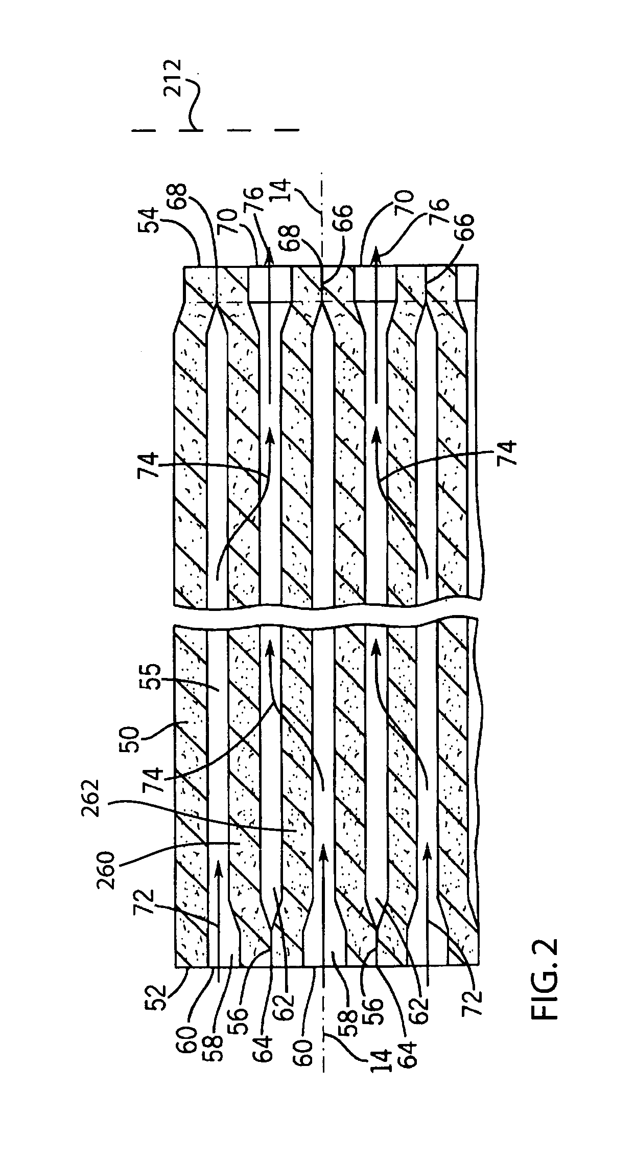
[0042] The following description of FIGS. 1-10 is taken from incorporated U.S. Pat. No. 6,482,247 regarding FIGS. 1, 2, 16-23, respectively.

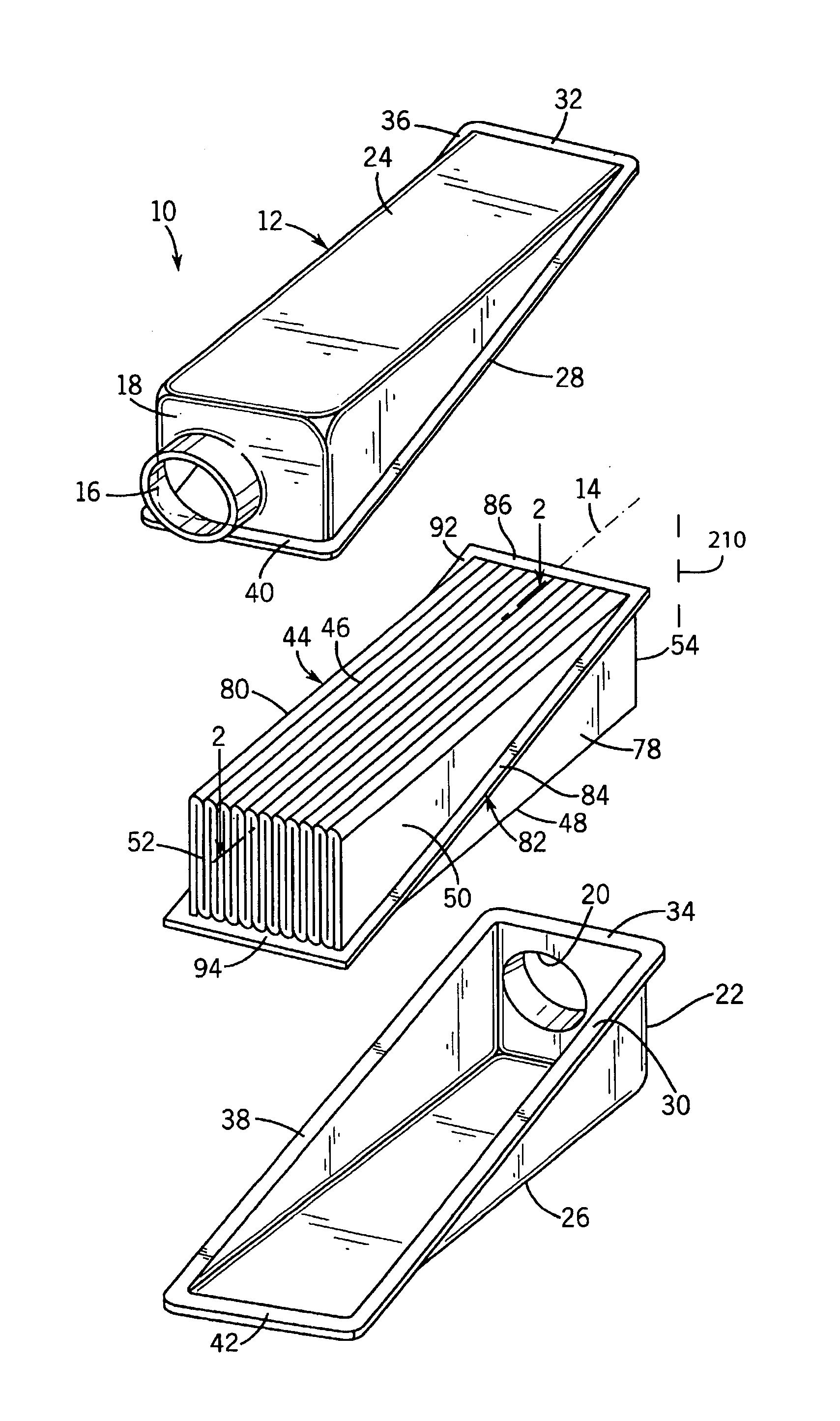
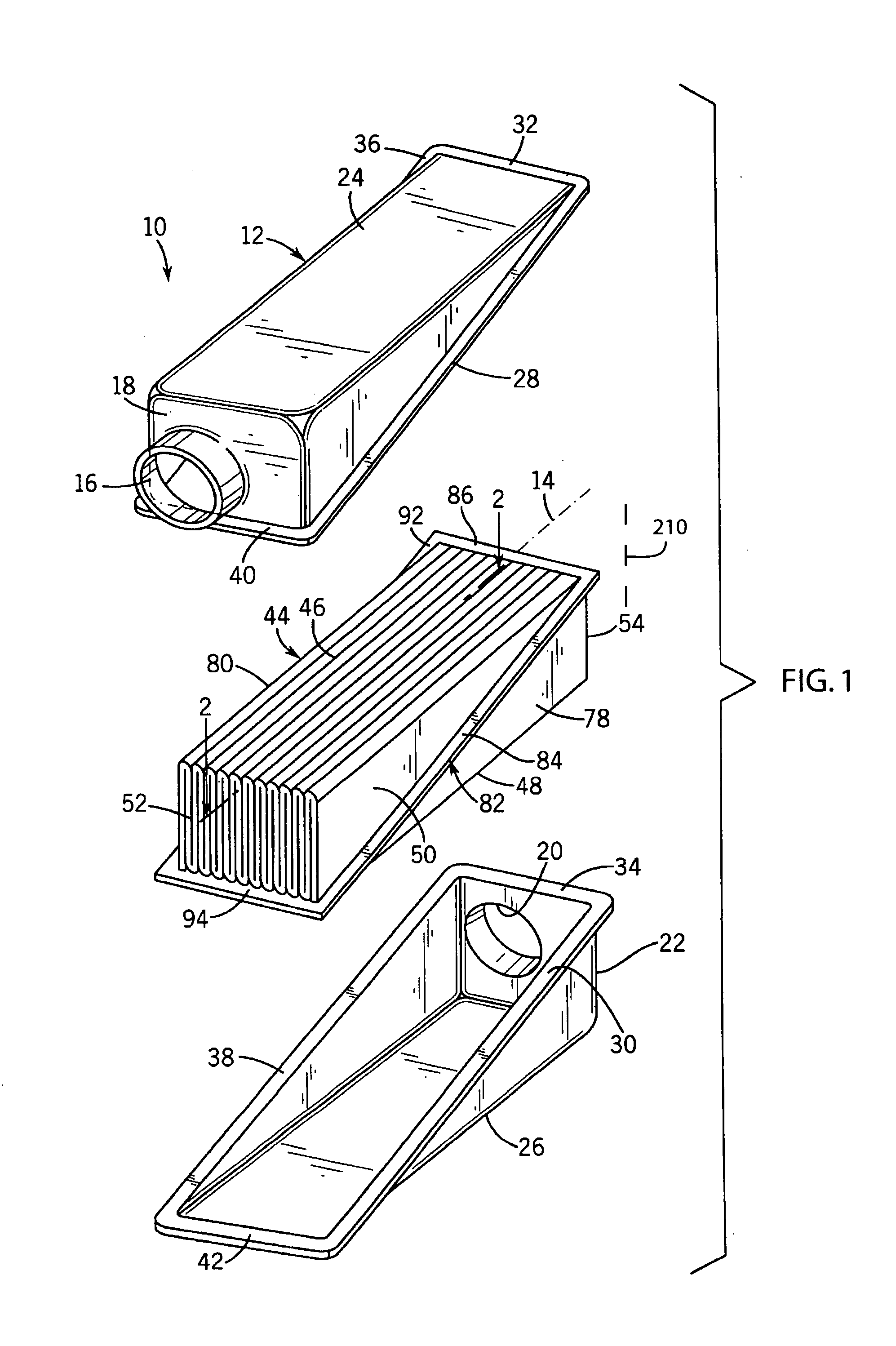
[0043]FIG. 1 shows a filter 10 including a housing 12 extending axially along axis 14 and having an inlet 16 at one axial end 18 of the housing and having an outlet 20 at a distally opposite axial end 22 of the housing. The housing is preferably plastic and provided by identical upper and lower half sections 24 and 26 mating along diagonal flanges 28, 30, lateral flanges 32, 34, diagonal flanges 36, 38, and lateral flanges 40, 42.

[0044] A pleated filter block is provided by pleated filter element 44 in the housing. The pleated filter element is pleated along a plurality of upper bend lines 46 and lower bend lines 48, which bend lines extend axially. The filter element has a plurality of wall segments 50 extending in serpentine manner between the upper and lower bend lines. The wall segments extend axially between upstream ends 52 at ...


PUM

PropertyMeasurementUnit
Angleaaaaaaaaaa
Flow rateaaaaaaaaaa
Pressure dropaaaaaaaaaa

Abstract

A direct flow filter has seal tips alternately sealing upstream and/or downstream ends of wall segments to each other to define first and second sets of flow channels and protecting the ends of the wall segments from damage, including upstream ends from incoming debris, and providing structural support withstanding high flow rates and improving flow by means of the geometry of the seal.

Description

BACKGROUND AND SUMMARY [0001] The invention relates to fluid filters, and more particularly to direct flow filters. [0002] The invention arose during continuing development efforts relating to direct flow filters. The filtration industry, including for automotive application, is driven towards more efficient space utilization, e.g. eliminating large open areas within a filter element and / or within a filter housing between the filter element and the housing, which is particularly desirable in space constrained areas such as behind the cabin or under the hood of vehicles. Direct flow filters are effective for this purpose. A direct flow filter filters fluid flowing along an axial flow direction and includes a pleated filter element having a plurality of pleats defined by wall segments extending along a transverse direction between first and second sets of pleat tips at first and second sets of axially extending bend lines, the transverse direction being perpendicular to the axial dire...

Claims


Application Information

Patent Timeline
IPC IPC(8): B01D46/40
CPCB01D46/125B01D46/2411B01D2275/201B01D2271/02B01D46/521B01D46/121
Inventor TERRES, MARK A.JANIKOWSKI, ERIC A.
Owner FLEETGUARD INC
Why Eureka
Try Eureka