
Dynamic render algorithm selection

a dynamic rendering and algorithm technology, applied in the direction of static indicating devices, instruments, image generation, etc., can solve the problems of large amount of ram required, large amount of ram is relatively costly, and over 100 mbytes

Inactive Publication Date: 2006-03-30
CANON KK
View PDF21 Cites 31 Cited by
  • Summary
  • Abstract
  • Description
  • Claims
  • Application Information

AI Technical Summary

Benefits of technology

[0017] It is an object of the present invention to substantially overcom...

Problems solved by technology

There are two problems with the Painter's algorithm.
For high-resolution color printers the amount of RAM required can be very large, typically in excess of 100 Mbytes.
Large amounts of RAM are relatively costly and are difficult to run at high speed.
The second problem is that many pixels in the framestore are over-painted (re-rendered) by later objects, often many times. Painting these pixels with the earlier objects can result in considerable wasted computation effort and wasted memory bandwidth.
The problems with the Painter's algorithm result in lower rendering performance.
There are some penalties with this technique, however.
Also, the technique of banding does not solve the problem of over-painting.
In some implementations, the overhead of dividing the page into bands can also result in a performance penalty.
This technique overcomes the large framestore problem, but however still suffers from the over-painting problem.
However, only relatively few of those objects are present (“active”) on each individual pixel.
However, the pixel-sequential renderer also has some problems.
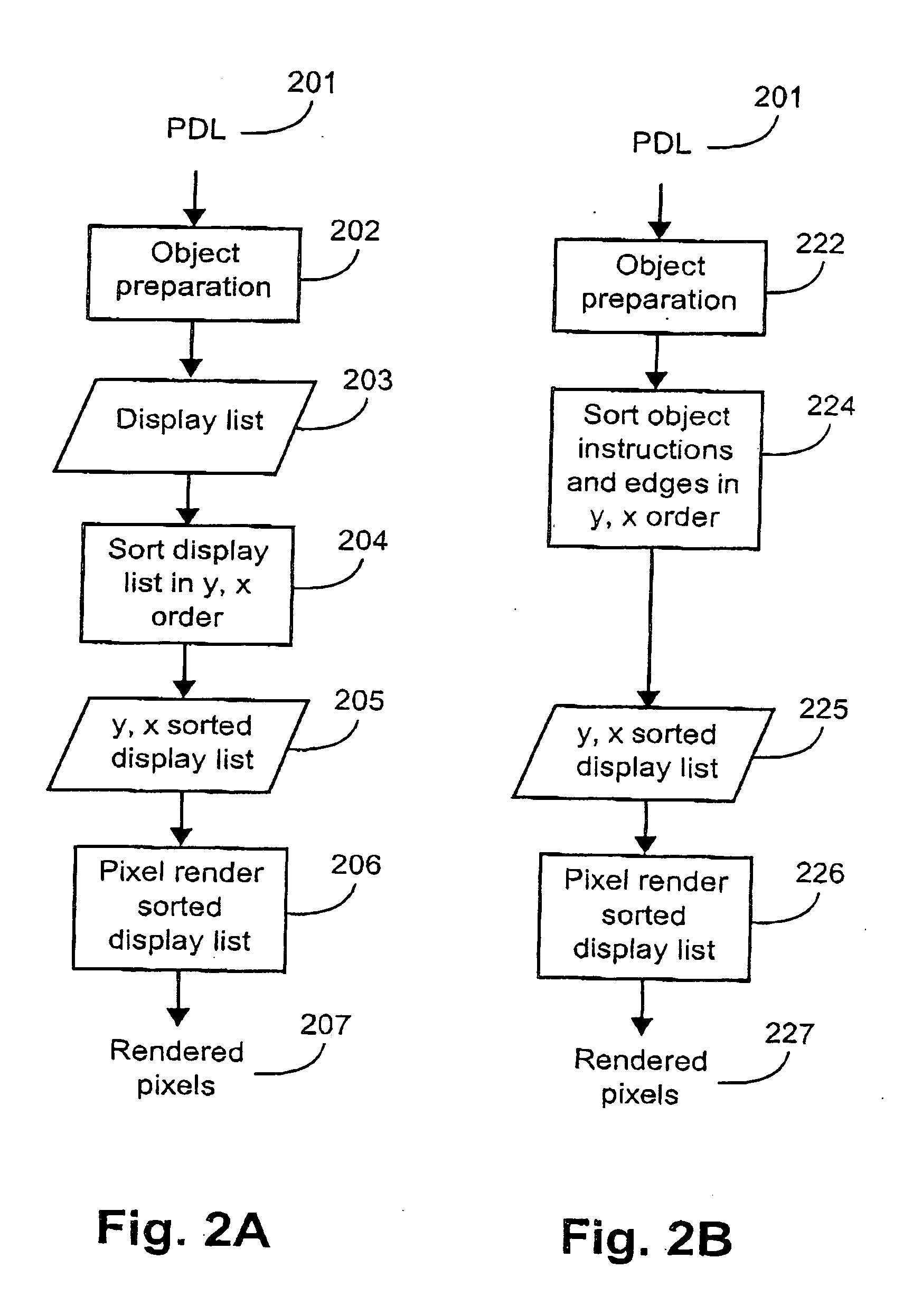
Object data which generates many closely-packed edge crossings, or which causes many active levels at one time, or which generates a large amount of fill table data, causes the pixel-sequential renderer to perform poorly.
But often applications produce PDLs or intermediate formats which contain problematic object data.
In this case, the rendering system must accept the problematic object data, which in turn causes poor performance.

Method used


Image

  • Dynamic render algorithm selection
  • Dynamic render algorithm selection
  • Dynamic render algorithm selection

Examples


Embodiment Construction

[0077] Some portions of the description which follows are explicitly or implicitly presented in terms of algorithms and symbolic representations of operations on data within a computer memory. These algorithmic descriptions and representations are the means used by those skilled in the data processing arts to most effectively convey the substance of their work to others skilled in the art. An algorithm is here, and generally, conceived to be a self-consistent sequence of steps leading to a desired result. The steps are those requiring physical manipulations of physical quantities. Usually, though not necessarily, these quantities take the form of electrical or magnetic signals capable of being stored, transferred, combined, compared, and otherwise manipulated. It has proven convenient at times, principally for reasons of common usage, to refer to these signals as bits, values, elements, symbols, characters, terms, numbers, or the like.

[0078] It should be borne in mind, however, tha...


PUM


Abstract

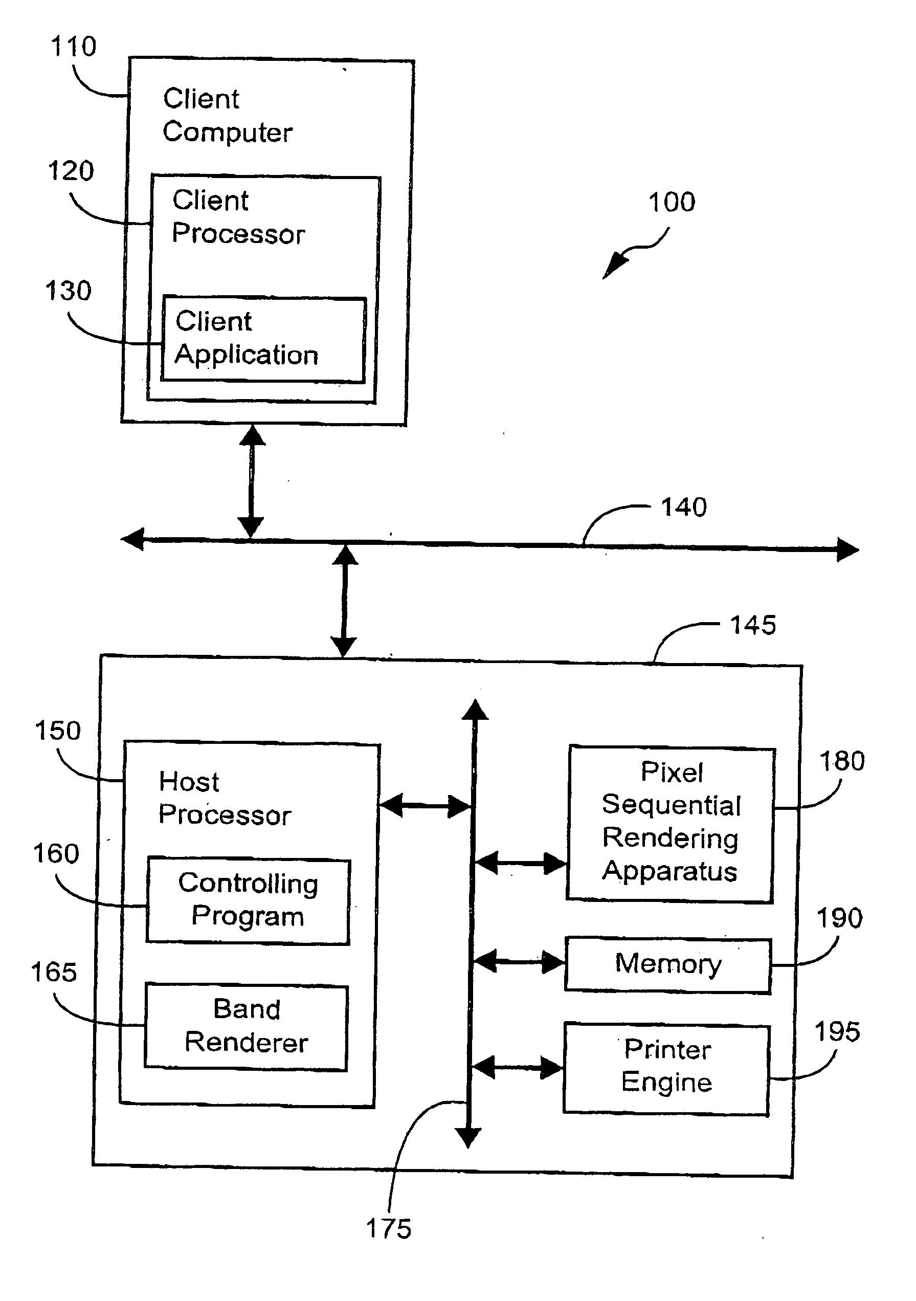
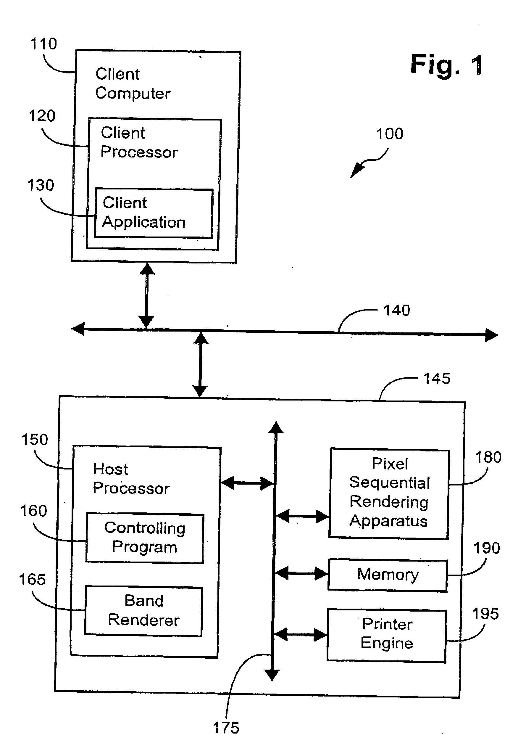
A method of rendering a sequence of graphical objects, where two or more different renderers are available and one of the renderers is designated as a currently-used renderer, includes the steps of receiving a current object in the sequence of graphical objects, adding the current object to a set of recently-received objects, and checking whether any one of a predetermined group of patterns of objects is present in the set, each pattern having an associated indication of the suitability of the available renderers for the pattern, the suitability being dependent on a time taken to render the pattern. The method further includes the steps of determining a suitable renderer from the available renderers using a pattern and associated indication identified in the checking step, and switching from the currently-used renderer to the suitable renderer if the suitable renderer is different from the currently-used renderer.

Description

CROSS-REFERENCE TO RELATED PATENT APPLICATIONS [0001] This application claims the right of priority under 35 U.S.C. § 119 based on Australian Patent Application No 2004905560, filed 24 Sep. 2004, which is incorporated by reference herein in its entirety as if fully set forth herein.FIELD OF INVENTION [0002] The current invention relates to rendering graphical object descriptions for printing, storage or display, and in particular to swapping renderers while rendering graphical object descriptions for printing, storage or display. BACKGROUND [0003] There are many methods of converting object descriptions to pixels. All such methods are called “rendering”. Object descriptions may be presented ill Page Description Languages (PDLs) such as PCL, Postscript or PDF, or may be passed to tile renderer via some programming interface. In any case, the renderer receives objects, usually in drawing order (also referred to as priority or z-order). The renderer then converts the received objects i...

Claims


Application Information

Patent Timeline
IPC IPC(8): G06T1/00G06F15/00
CPCG06T11/40G06T2210/32G06T15/00
Inventor HERCEG, MARIJAKELSEY, JULIAN BENJAMINMARTIN, MICHAEL ANTHONY
Owner CANON KK
Learn More