
Image forming apparatus and method

a technology of image forming apparatus and forming line, which is applied in the direction of printing, other printing apparatus, etc., can solve the problems of deteriorating line quality, affecting print quality, and affecting the quality of printing, so as to achieve the effect of restricting the decline in line quality

Inactive Publication Date: 2006-03-30
FUJIFILM CORP
View PDF2 Cites 9 Cited by
  • Summary
  • Abstract
  • Description
  • Claims
  • Application Information

AI Technical Summary

Benefits of technology

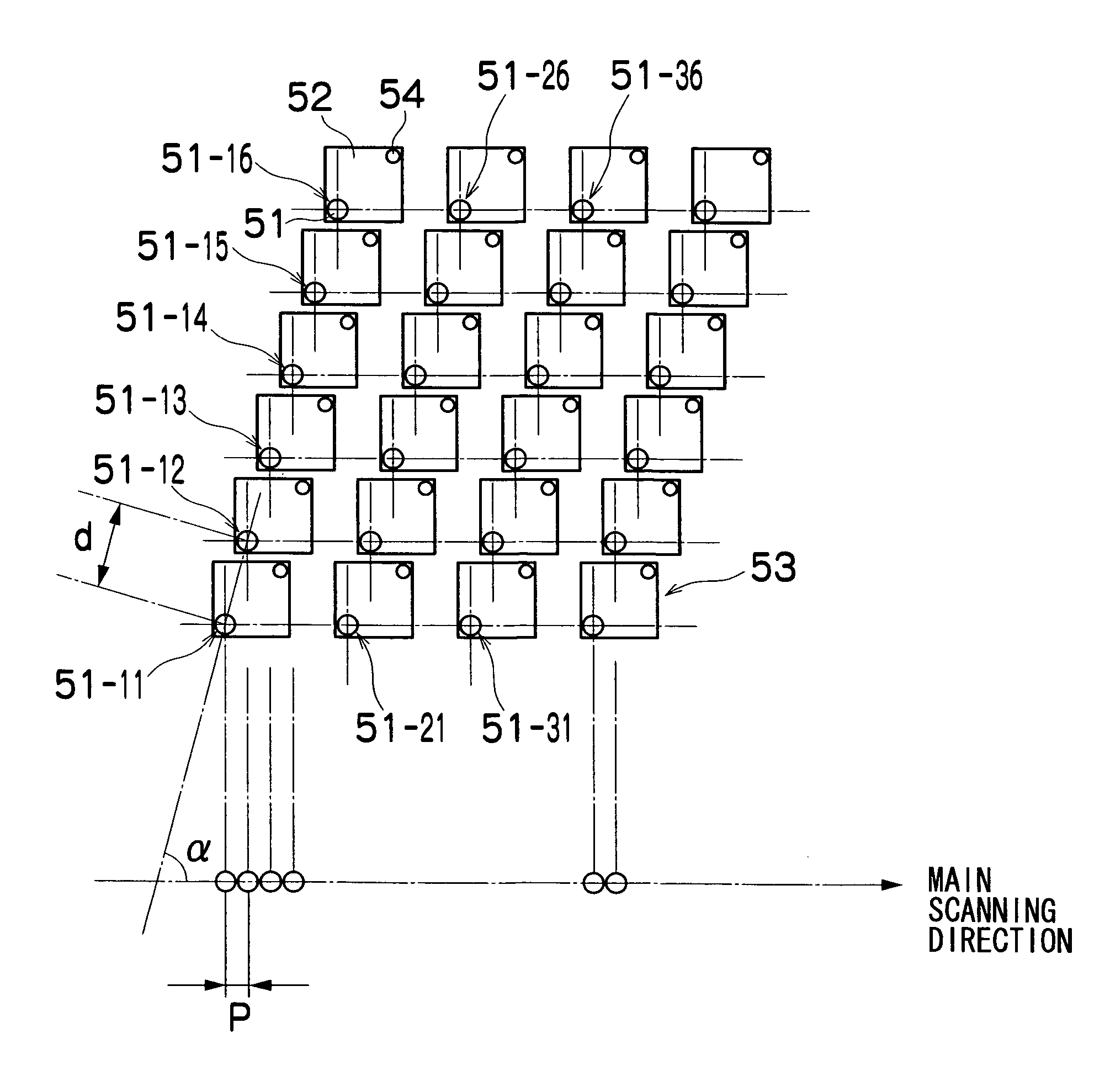
[0013] The present invention has been contrived in view of the foregoing circumstances, an object thereof being to provide an image forming method and apparatus which can restrict deterioration in line quality resulting from positional displacement of dots in a direction perpendicular to the relative movement direction of a recording head and recording medium (which corresponds to the nozzle row direction described above) due to an ejection direction abnormality in a nozzle.

Problems solved by technology

In an inkjet recording apparatus (printer), there is a problem in that the position of dots deposited on a recording medium may be displaced from their ideal positions (hereafter, this is referred to as “deposition position displacement”), due to causes such as variation in the ink ejection direction from the nozzles, displacement of the nozzle positions, displacement of the positions of the respective color heads, and so on., and consequently, print quality is impaired.
In particular, when printing lines in graphs, figures or the like, or text, the decline in quality caused by displacement of the dot positions from ideal positions is particularly severe, and becomes a very important problem in terms of the quality of the printer (hereinafter, the quality of lines in graphs or figures, and text, is referred to as “line quality”).
These projection and depression in the row of dots cause deterioration in line quality.
As described above, the depressions and projections in the dot row occurring as a result of deposition position displacement of the dots is a major cause of deterioration in line quality.
However, in the case of deposition position displacement in a direction (hereinafter referred to as the “nozzle row direction”) which is perpendicular to the aforementioned direction, it is not possible to cause a dot to be deposited at the ideal position, even if the ejection timing is altered.

Method used


Image

  • Image forming apparatus and method
  • Image forming apparatus and method
  • Image forming apparatus and method

Examples


Embodiment Construction

General Configuration of Inkjet Recording Apparatus

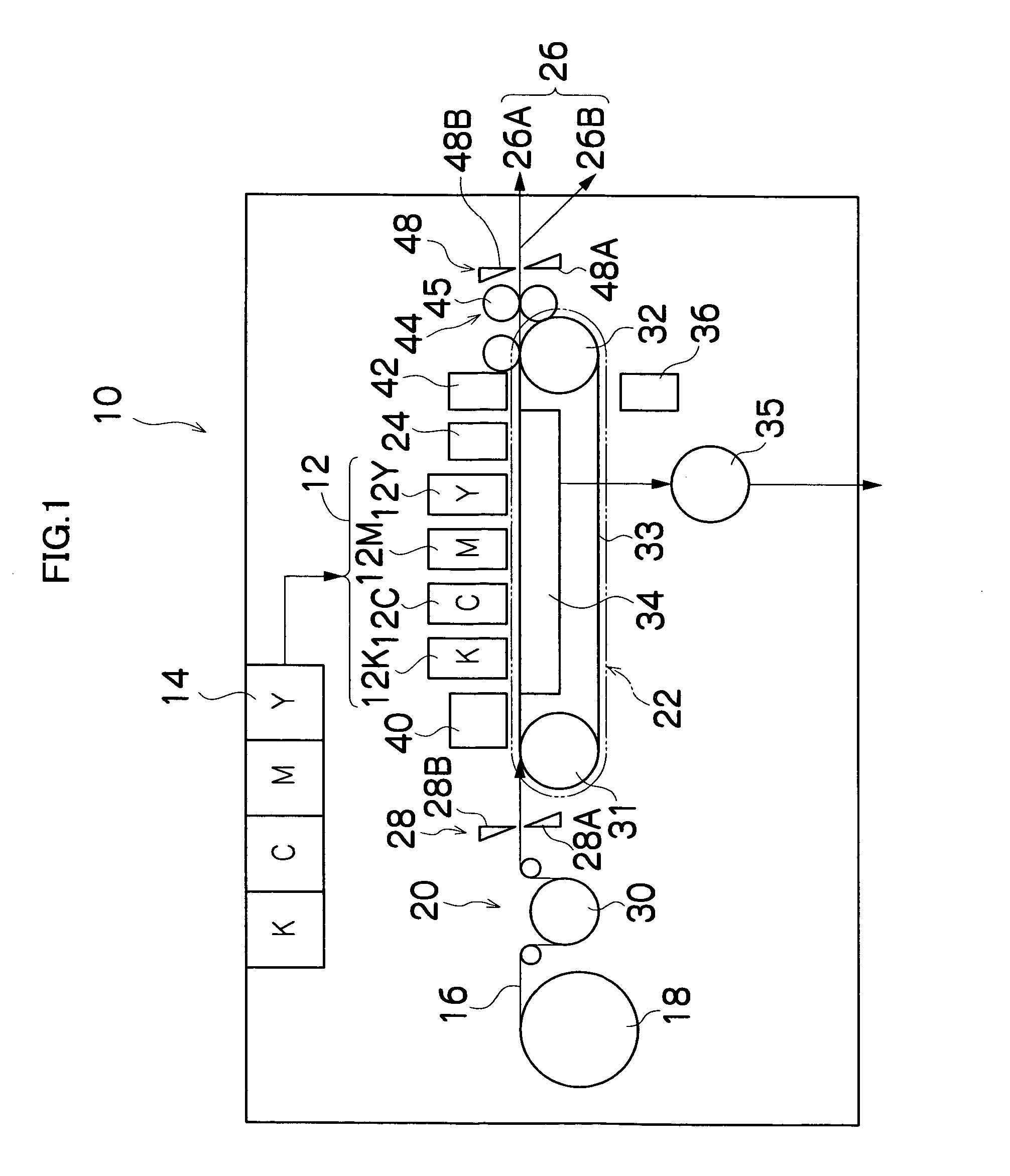
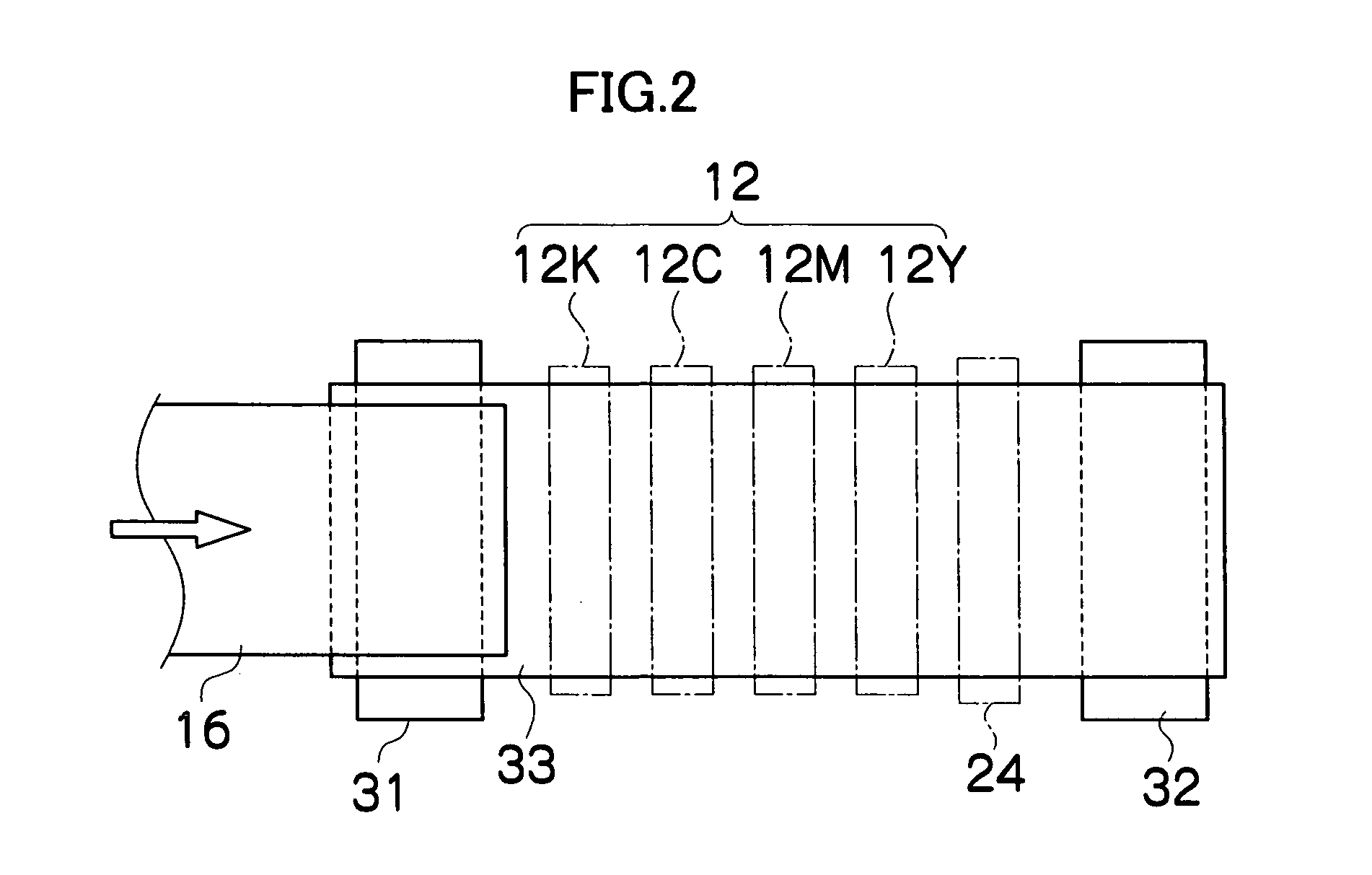
[0054]FIG. 1 is a general configuration diagram of an inkjet recording apparatus showing one embodiment of an image forming apparatus according to the present invention. As shown in FIG. 1, the inkjet recording apparatus 10 comprises: a printing unit 12 having a plurality of inkjet recording heads (hereinafter referred to as “heads”) 12K, 12C, 12M, and 12Y provided for ink colors of black (K), cyan (C), magenta (M), and yellow (Y), respectively; an ink storing and loading unit 14 for storing inks of K, C, M and Y to be supplied to the print heads 12K, 12C, 12M, and 12Y; a paper supply unit 18 for supplying recording paper 16 which is a recording medium; a decurling unit 20 removing curl in the recording paper 16; a suction belt conveyance unit 22 disposed facing the nozzle face (ink-droplet ejection face) of the printing unit 12, for conveying the recording paper 16 while keeping the recording paper 16 flat; a print determination ...


PUM


Abstract

The image forming apparatus comprises: a recording head which includes a plurality of nozzles through which droplets of liquid are ejected to and deposited on a recording medium to form dots on the recording medium, the nozzles being arranged in a nozzle row; a conveyance device which causes the recording head and the recording medium to move relatively to each other by conveying at least one of the recording head and the recording medium in a relative movement direction; a storage device which, of information indicating an amount of deposition position displacement from an ideal deposition position of the dots formed by the droplets ejected from the nozzles, stores information about the amount of deposition position displacement in at least a direction perpendicular to the relative movement direction of the conveyance device; a line figure recognition processing device which carries out processing for recognizing line figures from image data for printing; an ideal line identification device which determines an ideal line obtained by linking centers of the respective dots formed when printing a line figure, assuming that there is absolutely no deposition position displacement produced by any of the nozzles, in respect of the line figure recognized by the line figure recognition processing device; and an ejection timing control device which, when printing a line figure, controls ejection timing of a defective nozzle which produces deposition position displacement in a direction perpendicular to the relative movement direction, according to the information about the amount of deposition position displacement stored in the storage device and the ideal line determined by the ideal line identification device, in such a manner that a deposition center position of a dot formed by a droplet ejected from the defective nozzle moves closer to the ideal line, along the relative movement direction.

Description

BACKGROUND OF THE INVENTION [0001] 1. Field of the Invention [0002] The present invention relates to an image forming apparatus and method, and more particularly, to droplet ejection control technology suitable for reducing deterioration in image quality caused by ejection errors in nozzles of a recording head (which may also be referred to as a “print head”) having nozzle rows in which a plurality of liquid ejection ports (nozzles) are arranged. [0003] 2. Description of the Related Art [0004] In an inkjet recording apparatus (printer), there is a problem in that the position of dots deposited on a recording medium may be displaced from their ideal positions (hereafter, this is referred to as “deposition position displacement”), due to causes such as variation in the ink ejection direction from the nozzles, displacement of the nozzle positions, displacement of the positions of the respective color heads, and so on., and consequently, print quality is impaired. In particular, when pr...

Claims


Application Information

Patent Timeline
IPC IPC(8): B41J29/38
CPCB41J2/2135
Inventor YAMANOBE, JUN
Owner FUJIFILM CORP
Learn More