Read sensor having an in-stack biasing structure and an AP coupled free layer structure for increased magnetic stability

a free layer and sensor technology, applied in the field of read sensors of magnetic heads, can solve the problems of unstable magnetic spin of the free layer, difficult to accurately control the current fabrication method, and produce magnetic noise in response, and achieve the effect of increasing the stability of the ap coupled free layer structur

Inactive Publication Date: 2006-03-30
HITACHI GLOBAL STORAGE TECH NETHERLANDS BV
View PDF20 Cites 30 Cited by
  • Summary
  • Abstract
  • Description
  • Claims
  • Application Information

AI Technical Summary

Benefits of technology

This patent describes how two layers can be used together to create a stable system where they are attracted to each other by their magnetic moments. A thicker layer helps make this attraction stronger, which makes it more difficult for the layers to separate during use. This design also includes a special material between the layers called a non-magnetic spacer layer, which further strengthens the connection between them. Overall, this technology allows for better control over the movement and separation of these layers when used in practical applications like electronics.

Problems solved by technology

The technical problem addressed in this patent text is the need for a more effective method of stabilizing the free layer in a read sensor structure. The current methods of using an in-Stack biasing structure or a ferromagnetic biasing layer to stabilize the free layer are not always effective, and there is a need for a small magnetic moment for the free layer to magnetically stabilize it. The in-Stack biasing Scheme and the Tunnelling Biasing Scheme are also discussed. The patent text aims to overcome these deficiencies and improve the effectiveness of the in-Stack Biasing Scheme.

Method used


Image

  • Read sensor having an in-stack biasing structure and an AP coupled free layer structure for increased magnetic stability
  • Read sensor having an in-stack biasing structure and an AP coupled free layer structure for increased magnetic stability
  • Read sensor having an in-stack biasing structure and an AP coupled free layer structure for increased magnetic stability

Examples


Embodiment Construction

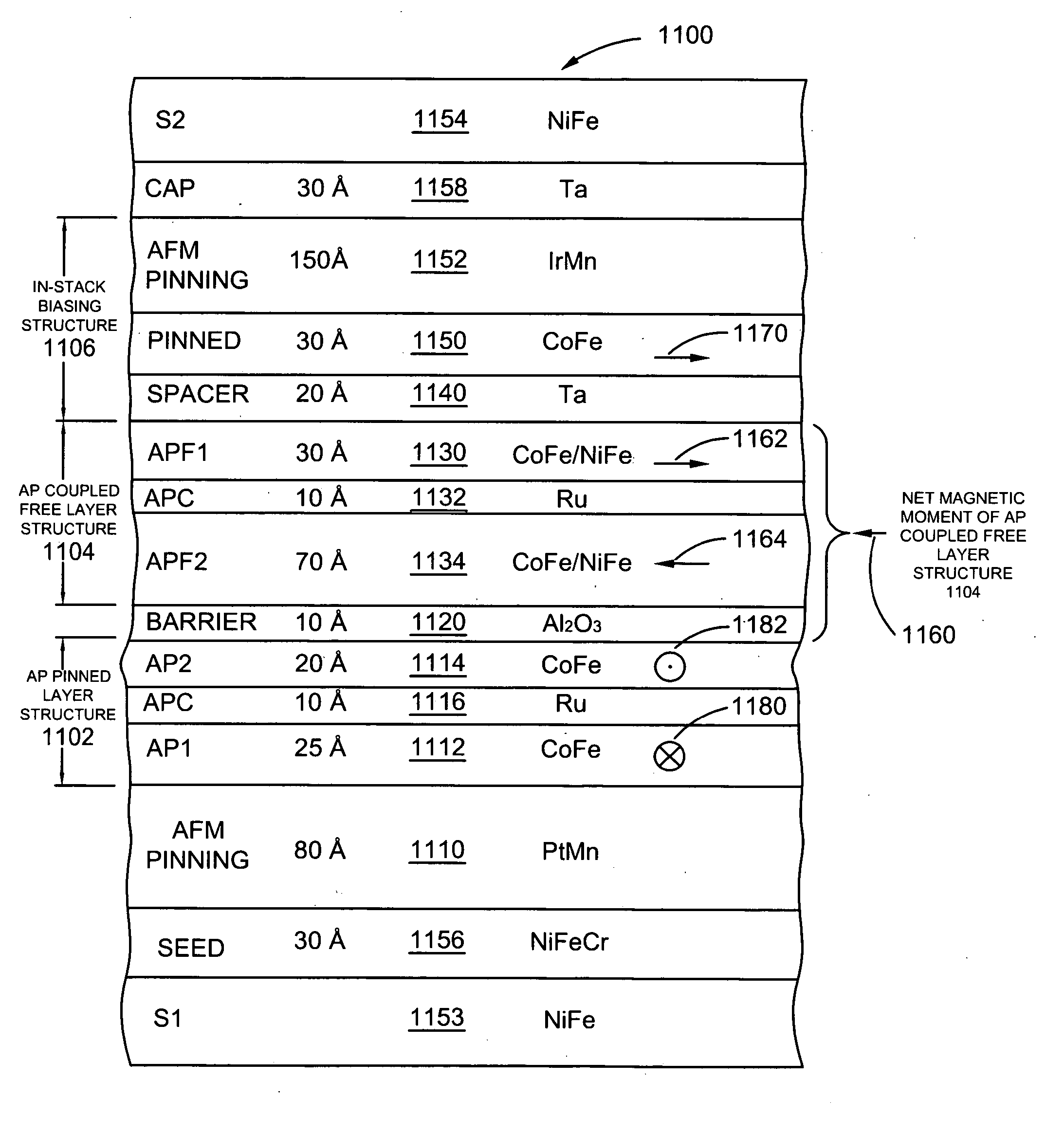
[0033] A magnetic head includes first and second shield layers and a read sensor formed between and in electrical contact with the first and second shield layers, where the read sensor is of the current-perpendicular-to-the-plane (CPP), current-in-to-the-plane (CIP) or tunnel valve type sensor. The read sensor includes an antiparallel (AP) coupled free layer structure, an in-stack biasing structure which stabilizes the AP coupled free layer structure and a nonmagnetic spacer layer formed between the in-stack biasing layer and the AP coupled free layer structure. The AP coupled free layer structure comprises a first AP coupled free layer adjacent to the nonmagnetic spacer layer, a second AP coupled free layer and an antiparallel coupling (APC) layer formed between the first and the second AP coupled free layers. The net moment of the AP coupled free layer structure has an antiparallel edge magnetostatic coupling with the in-stack biasing structure. At the same time the first AP coupl...


PUM


Abstract

Current-perpendicular-to-the-plane (CPP), current-in-to-the-plane (CIP), and tunnel valve type sensors are provided having an antiparallel (AP) coupled free layer structure, an in-stack biasing structure which stabilizes the AP coupled free layer structure and a nonmagnetic spacer layer formed between the in-stack biasing layer and the AP coupled free layer structure. The AP coupled free layer structure has a first AP coupled free layer adjacent to the nonmagnetic spacer layer, a second AP coupled free layer, and an antiparallel coupling (APC) layer formed between the first and the second AP coupled free layers. The net moment of the AP coupled free layer structure has an antiparallel edge magnetostatic coupling with the in-stack biasing structure. At the same time, the first AP coupled free layer has an antiparallel exchange coupling with the second AP coupled free layer. By forming the second AP coupled free layer with a thickness greater than a thickness of the first AP coupled free layer, the AP coupled free layer structure has a net magnetic moment in the direction of the second AP coupled free layer moment. The non-magnetic spacer layer is chosen so that first AP coupled free layer has a parallel interlayer (Neel or Orange-peel or positive exchange) coupling with the in-stack biasing structure, so that the interlayer coupling adds to the edge magnetostatic coupling to increase a stability of the AP coupled free layer structure.

Description


Claims


Application Information

Patent Timeline
Owner HITACHI GLOBAL STORAGE TECH NETHERLANDS BV
Why Eureka
Try Eureka