
Data recording/reproducing system using optical disk apparatus

a technology of optical disk and recording system, applied in the field of data recording/reproducing system, can solve the problems of cpu consumption, data cannot be appropriately recorded on a medium, complicated system structure, etc., and achieve the effect of power saving and easy and reliable recording of video signal and audio signal

Inactive Publication Date: 2006-03-30
TEAC CORP
View PDF12 Cites 13 Cited by
  • Summary
  • Abstract
  • Description
  • Claims
  • Application Information

AI Technical Summary

Benefits of technology

[0010] The present invention advantageously provides a system equipped with an optical disk apparatus, which is capable of recording a video signal and an audio signal easily and reliably while achieving power saving.
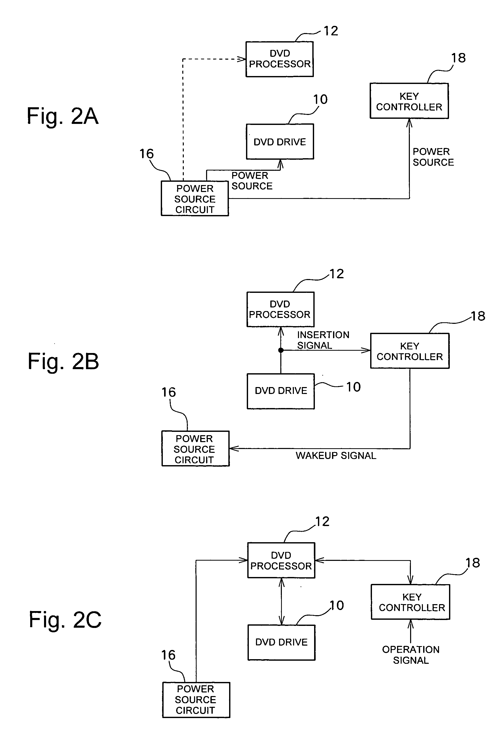
[0011] The present also advantageously provides a system which can easily recover from a sleep state to a normal operation state by mean of insertion of a medium and also can recover from the sleep state and start a desired operation by operation of an operation switch, such as a recording key.

Problems solved by technology

However, with the above technology, in order to start video recording, the system is controlled to remain in a REC PAUSE state in which recording can be started any time, which is undesirable from a viewpoint of power saving.
Accordingly, there is a possibility that data cannot be recorded on a medium appropriately in a system in which recording is started merely by using input of a video signal and an audio signal as a trigger as described above.
With this system, however, in order to notify the controller of the fact that a medium is inserted into the DVD drive, it is necessary to connect the DVD drive and the controller via an additional signal line, which results in a more complicated system structure.
This structure, however, results in the CPU consuming a great amount of power, and is therefore undesirable from the perspective of reducing power consumption.

Method used


Image

  • Data recording/reproducing system using optical disk apparatus
  • Data recording/reproducing system using optical disk apparatus
  • Data recording/reproducing system using optical disk apparatus

Examples


Embodiment Construction

[0019] A preferred embodiment of the present invention will be described in detail with reference to the accompanying drawings.

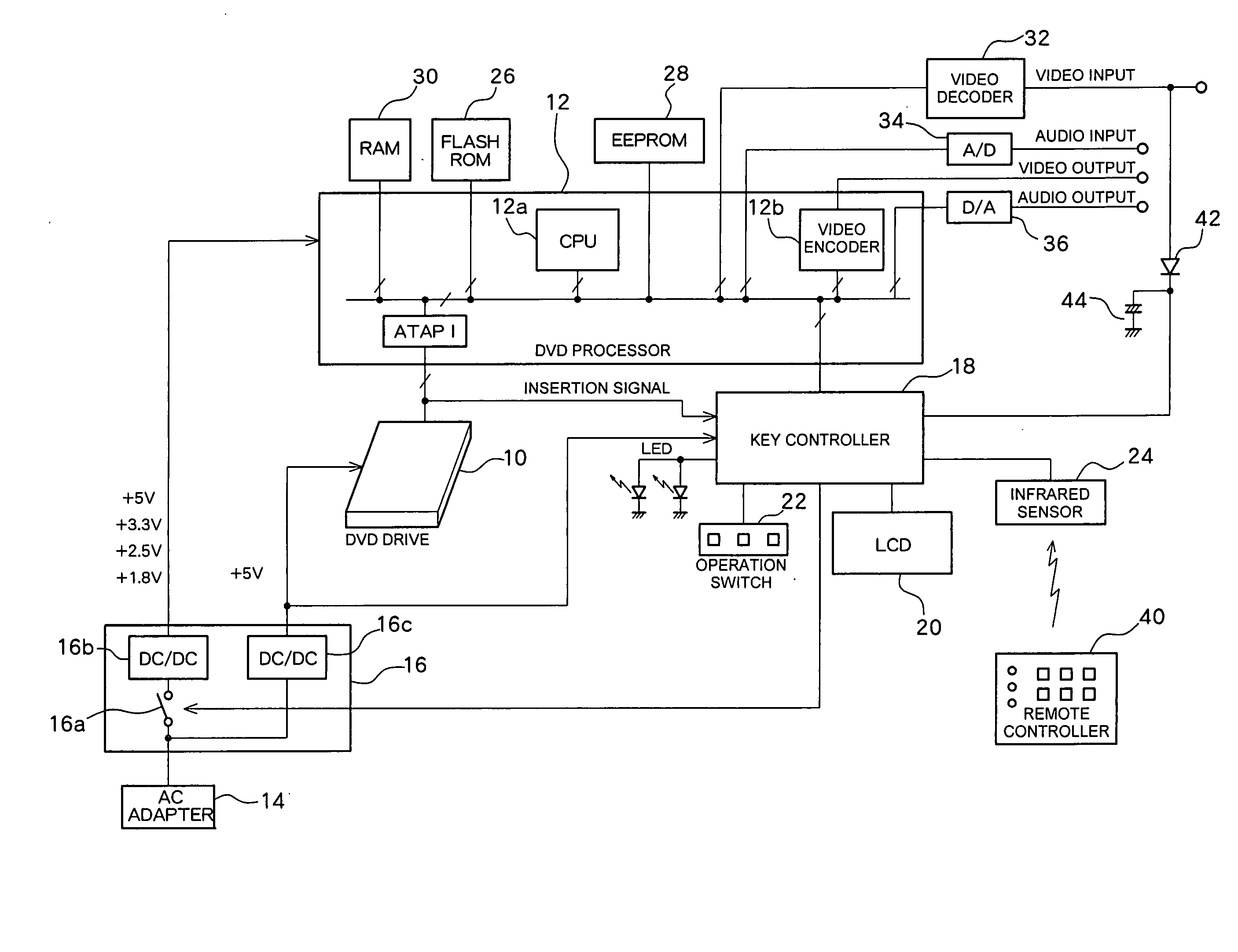
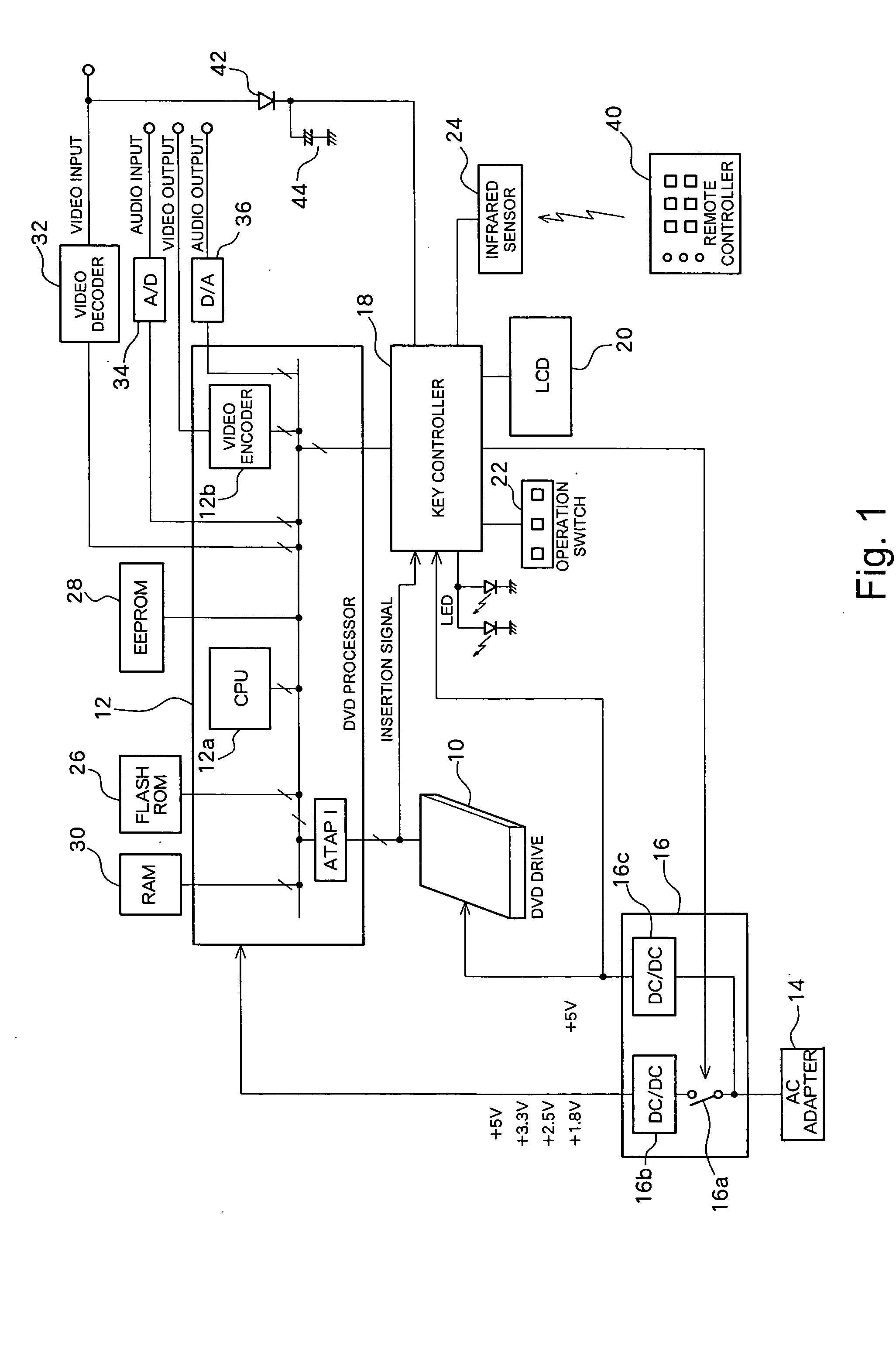
[0020]FIG. 1 shows a structure of a portable DVD recorder system according to the preferred embodiment of the present invention.

[0021] A DVD drive 10 performs recording and reproduction of data with respect to a DVD. Data to be recorded is supplied from a DVD processor 12, and data reproduced from the DVD is, in turn, supplied to the DVD processor 12. The DVD drive 10 may be a so-called combo drive which performs recording and reproduction with respect to a CD in addition to recording and reproduction with respect to a DVD. The DVD drive 10 operates by a power source voltage supplied from a power source circuit 16. The mode in which the DVD drive 10 operates is controlled by the controller of the DVD drive 10, independent of the DVD processor 12 and other sections of the system. Specifically, in the present embodiment, the DVD drive 10 has four operation (...


PUM

PropertyMeasurementUnit
voltageaaaaaaaaaa
voltageaaaaaaaaaa
voltageaaaaaaaaaa

Abstract

A DVD recorder system having a sleep state. When a predetermined period of a non-operation state has elapsed, a key controller switches the state of a power source circuit to interrupt voltage supply, thereby causing the system to shift to the sleep state. In this state, when a signal is input from the video input terminal, the key controller controls the power source circuit to turn ON, thereby causing the system to shift to the normal state. After recovery to the normal state, a DVD processor provides instructions to a DVD drive in accordance with recording conditions which are prestored in an EEPROM, and supplies an input video signal to the DVD drive so as to start recording. Also, when a medium is inserted in the DVD drive, the key controller detects an insertion signal to control the power source circuit to turn ON, thereby causing the system to return to the normal state.

Description

BACKGROUND OF THE INVENTION [0001] 1. Field of the Invention [0002] The present invention relates to a data recording / reproducing system, and more particularly to a system including an optical disk apparatus, which has a normal state which is a normal operational state and a sleep state which is a power saving state. [0003] 2. Description of Related Art [0004] Many computer systems and DVD recorder systems including an optical disk apparatus (an optical disk drive) such as a CD drive and a DVD drive have been developed. For such systems, it is desirable that video and audio data can be recorded in a simple manner whenever desired by a user. [0005] Japanese Patent Laid-Open Publication No. 2000-132954 describes a technology in a system concerning video cassette recorders (VCRs). Specifically, in the described technology, a VCR is connected to a set top box (STB), and on turning the STB ON at a time point which has been preset in a timer, levels of a synchronization signal, a video si...

Claims


Application Information

Patent Timeline
Patent Type & Authority Applications(United States)
IPC IPC(8): G11B19/02G11B20/00
CPCG11B19/10G11B19/06
Inventor UMEHARA, SHINJIHONGO, RYOTAROHONDA, TAKAYUKINAKAHASHI, TERUYOSHITSUYUGUCHI, HIROSHI
Owner TEAC CORP
Learn More