Polymeric shell adherently supported by a liner and a method of manufacture

Active Publication Date: 2006-03-30
ANSELL HEALTHCARE PRODS
19 Cites 59 Cited by

AI-Extracted Technical Summary

Problems solved by technology

The penetration of the aqueous latex emulsion into the dressed liner results in ‘strike-through,’ or “penetration,” which creates an unsightly appearance of the supported product and makes the article more rigid and less flexible.
However, the chemical resistance of the polymeric shell is generally inadequate due to poor coverage of the latex emulsion over the liner and may have holes in the latex layer where the fibers of the liner cross.
A further and perhaps more serious consequence of coating over a knitted fabric is the possibility that the resultant polymeric film is compromised, resulting in a non-uniform...

Benefits of technology

[0011] The present invention provides an article comprising at least one cured, liquid-impervious polymeric shell substantially free from defects; at least one liner; and a non-tacky, thermoplastic adhesive layer placed between the at least one shell and the at least one liner. The adhesive layer is...

Abstract

An article comprising at least one cured, liquid-impervious polymeric shell substantially free from defects, at least one liner, and a non-tacky, thermoplastic adhesive layer between the shell and the liner, wherein the adhesive layer is melted and solidified to create a non-tacky bond between the shell and the liner, which can be moisture-absorbing or cut-resistant, whereby the liner supports and limits stretch ability of the shell, thereby preventing adhesive delamination between the adhesive layer and either of the shell and/or the liner; a method for the manufacture of an article comprising a supported, polymeric shell, such as a glove, a gauntlet, an apron, or a boot, comprising providing a cured, liquid-impervious, polymeric shell, providing a knitted/woven liner, incorporating a non-tacky, thermoplastic adhesive layer between the shell and the liner, such as by hot-melt spraying, dry-powder spraying or fiber-coating, creating intimate contact between the shell, the adhesive layer, and the liner, subjecting the shell, the adhesive layer, and the liner to infrared radiation to melt the adhesive layer and create a bond between the shell and the liner, and cooling the shell; as well as other methods.

Application Domain

DiagnosticsGloves +14

Technology Topic

Fiber coatingEngineering +5

Image

  • Polymeric shell adherently supported by a liner and a method of manufacture
  • Polymeric shell adherently supported by a liner and a method of manufacture
  • Polymeric shell adherently supported by a liner and a method of manufacture

Examples

  • Experimental program(2)

Example

Example 1
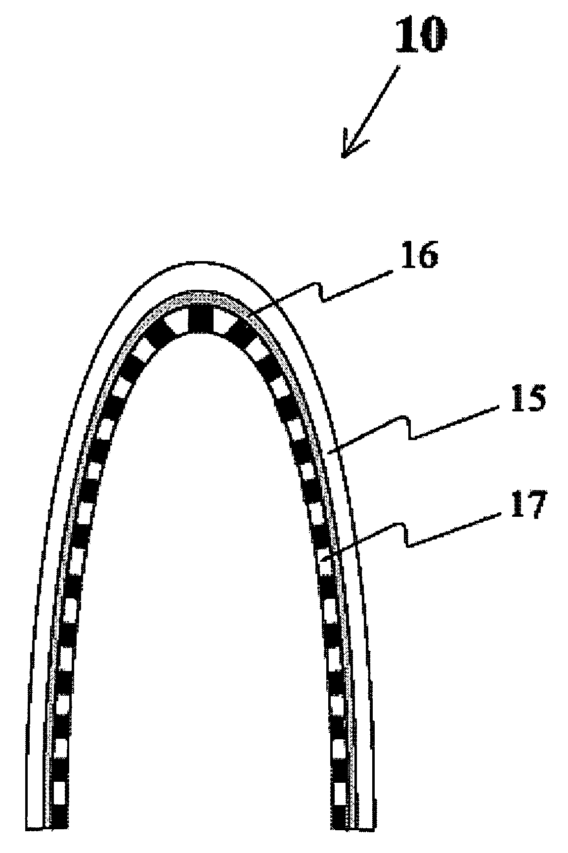
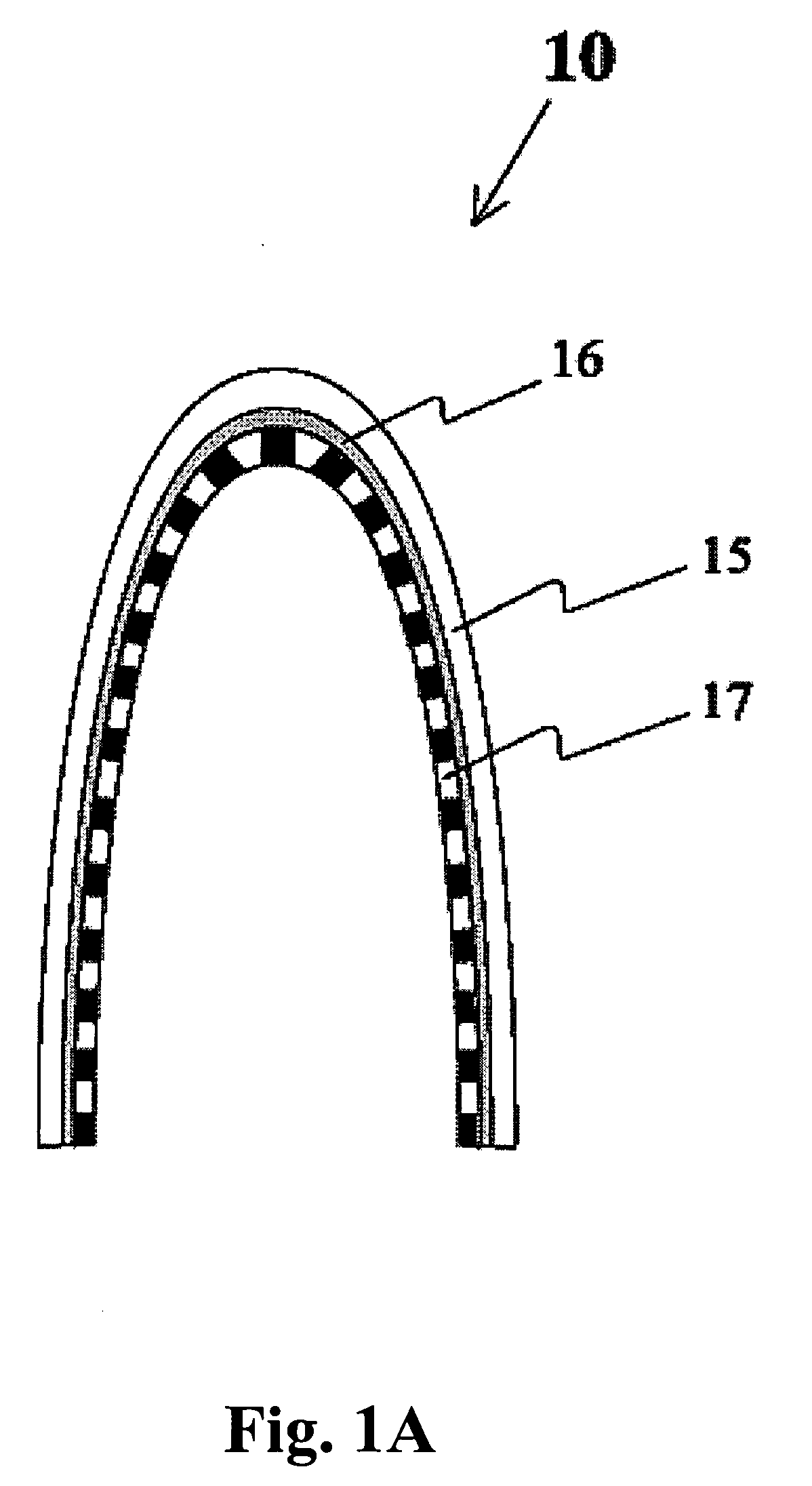
[0101] A nitrile polymeric shell was prepared by conventional dipping in an aqueous latex emulsion, using a coagulant to gel the nitrile latex, and curing to crosslink the polymer. A layer of thermoplastic polyurethane adhesive was hot-melt sprayed on the nitrile polymeric shell by spraying approximately 3 grams of the adhesive for a pair of gloves. A conventional knitting process prepared a cotton liner. The liner was placed on the adhesive-coated polymeric shell and heated to 125° C. using an infrared heat source. The assembly was cooled. The liner was permanently bonded to the supporting knitted liner. The supported nitrile polymeric shell was kept in ambient moist air to cure and cross-link the thermoplastic polyurethane adhesive.

Example

Example 2
[0102] A strip from Example 1 was cut and evaluated for bond strength. The bond strength was measured using the test procedure BS EN IS02411:2000, “Rubber- or Plastics-Coated Fabrics. Determination of Coating Adhesive,” (B.S.I. Chiswick, High Road, London, United Kingdom). The peel strength was measured by literally peeling the liner apart from the polymeric shell. Each free end of the joined polymeric shell and liner was held in the jaws of a tensiometer, and opposing forces were applied to peel the two apart. The units of measurement are stated in Newton force (N) per 50 mm of peel width, that is, N/50 mm width of peel line. The article was characterized by a minimum peel strength of 35 N/50 mm width of peel line. More often, the peel strength exceeded 63 N/50 mm width, and the peeled sections were characterized by fragmented liner still attached to the polymeric shell, indicating that the liner provided support to the polymeric shell until the supporting liner fragmented.
[0103] The subject invention provides a supported polymeric shell characterized by a combination of properties including: [0104] a) a pinhole- or defect-free polymeric shell; [0105] b) the polymeric shell bonded to a liner using a thermoplastic adhesive layer placed between the polymeric shell and the liner; [0106] c) the adhesive layer being substantially tack-free at ambient temperature; [0107] d) the adhesive layer melting at a temperature below degradation temperature of the polymeric shell or the liner; and [0108] e) the bond between the polymeric shell and the liner achieved by heating to melt the adhesive layer placed between a liner and a polymeric shell and cooling the heated supported polymeric shell, [0109] wherein the bonded liner limits the stretchability of the polymeric shell, thereby preventing the separation of the adhesive layer polymeric shell interface.
[0110] All references, including publications, patent applications, and patents, cited herein are hereby incorporated by reference to the same extent as if each reference were individually and specifically indicated to be incorporated by reference and were set forth in its entirety herein.
[0111] The use of the terms “a,”“an,”“the,” and similar referents in the context of describing the invention (especially in the context of the following claims) are to be construed to cover both the singular and the plural, unless otherwise indicated herein or clearly contradicted by context. Recitation of ranges of values herein are merely intended to serve as a shorthand method of referring individually to each separate value falling within the range, unless otherwise indicated herein, and each separate value is incorporated into the specification as if it were individually recited herein. All methods described herein can be performed in any suitable order unless otherwise indicated herein or otherwise clearly contradicted by context. The use of any and all examples, or exemplary language (e.g., “such as”) provided herein, is intended merely to better illuminate the invention and does not pose a limitation on the scope of the invention unless otherwise claimed. No language in the specification should be construed as indicating any non-claimed element as essential to the practice of the invention.
[0112] Preferred embodiments of this invention are described herein, including the best mode known to the inventors for carrying out the invention. It should be understood that the illustrated embodiments are exemplary only, and should not be taken as limiting the scope of the invention.

PUM

PropertyMeasurementUnit
Fraction0.005 ~ 0.2fraction
Melting point140.0°C
Electrical resistance

Description & Claims & Application Information

We can also present the details of the Description, Claims and Application information to help users get a comprehensive understanding of the technical details of the patent, such as background art, summary of invention, brief description of drawings, description of embodiments, and other original content. On the other hand, users can also determine the specific scope of protection of the technology through the list of claims; as well as understand the changes in the life cycle of the technology with the presentation of the patent timeline. Login to view more.
Why Eureka
Try Eureka