A technique of detecting the propagation environment of radio wave

Inactive Publication Date: 2006-03-30
BUFFALO CORP LTD
View PDF5 Cites 28 Cited by
  • Summary
  • Abstract
  • Description
  • Claims
  • Application Information

AI Technical Summary

Benefits of technology

[0021] The terminal device of the invention extracts the pattern representing a time-series variation in presence or absence of the detected radio wave, compares the extracted pattern with inherent patterns of radio wave transmitted from plural devices, which use the radio wave in the predetermined frequency band and include the base station, and thereby identifies the propagation environment of the radio w

Problems solved by technology

In the case of failed telecommunication by the terminal device, however, this prior art technique of detecting the propagation status of radio wave based on the intensity of an electric field can not identify the reason o

Method used


Image

  • A technique of detecting the propagation environment of radio wave
  • A technique of detecting the propagation environment of radio wave
  • A technique of detecting the propagation environment of radio wave

Examples


first embodiment

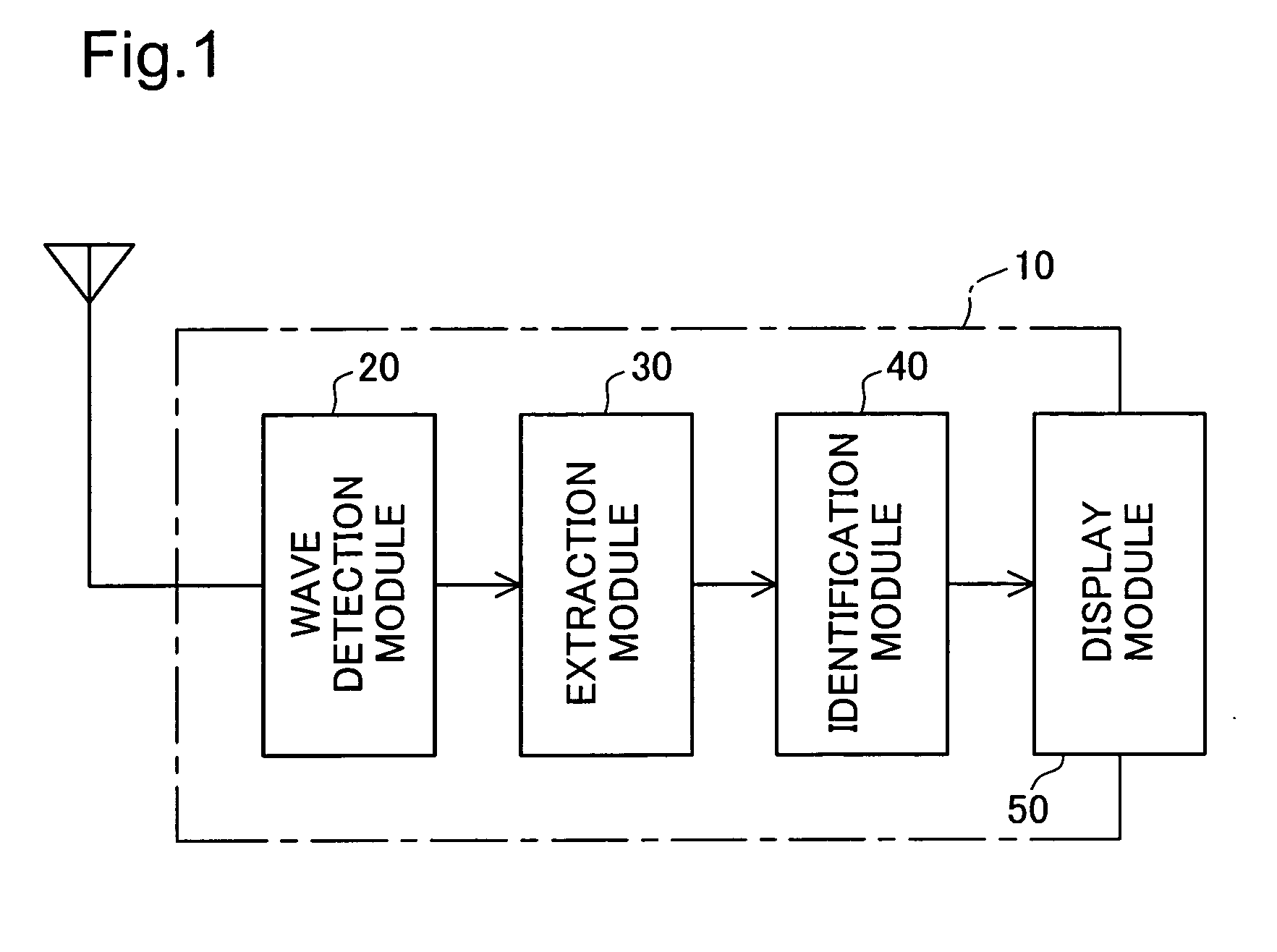
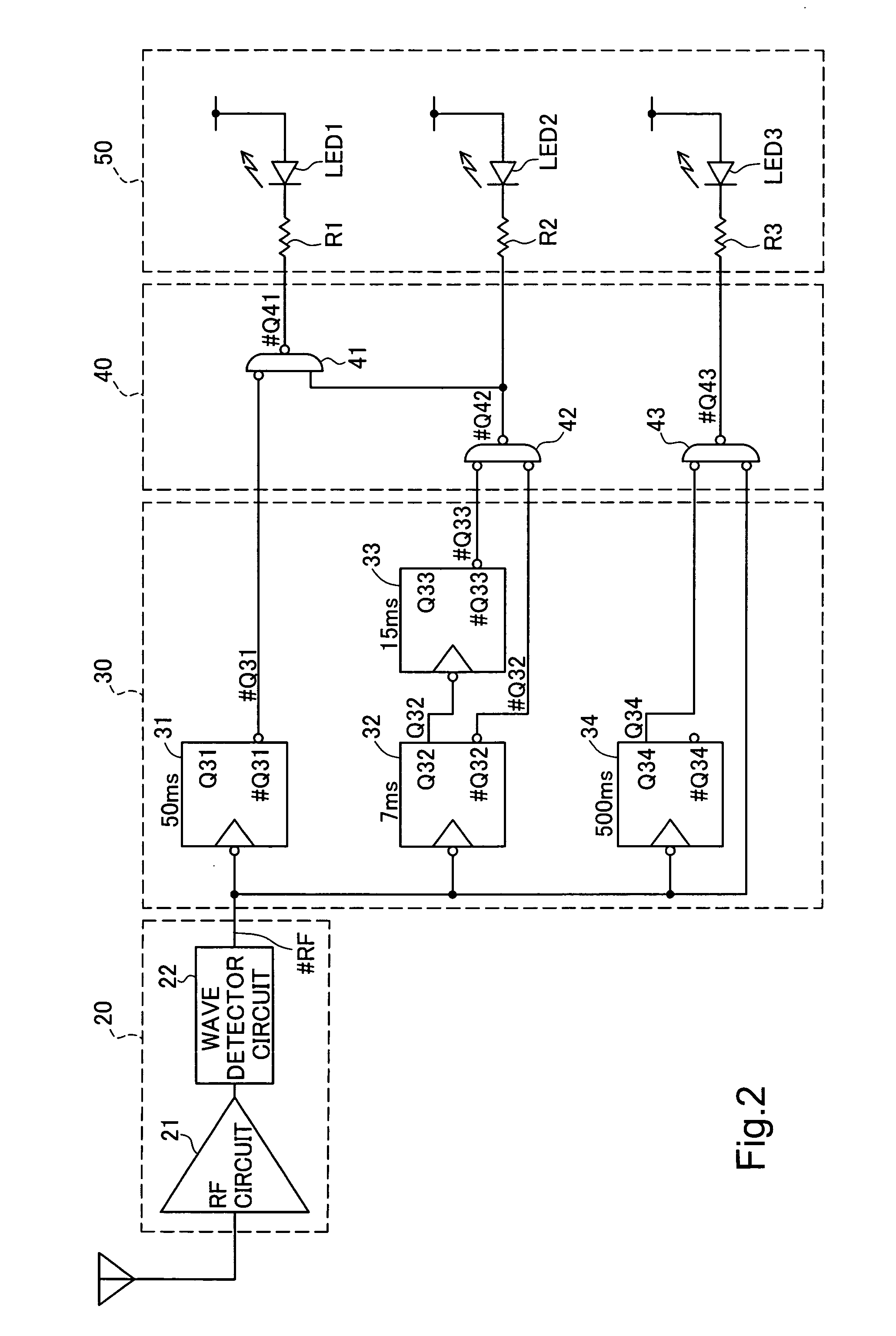
[0032]FIG. 1 is a functional block diagram showing the functions of a detector device 10 in the invention. The detector device 10 detects the propagation environment of radio wave used for telecommunications by a wireless LAN device, which is one of wireless communication devices. The detector device 10 has a wave detection module 20 that receives and detects radio wave in a predetermined frequency band used for telecommunications by the wireless LAN device, an extraction module 30 that binarizes a variation in intensity of the detected radio wave and extracts the binary data as a time series pattern, an identification module 40 that checks the extracted pattern and identifies the propagation environment of radio wave transmitted from the wireless LAN device, and a display module 50 that displays results of the identification. The detector device 10 of the embodiment detects the propagation environment of a wireless LAN in a frequency band of 2.4 GHz, which is conformity with the st...

second embodiment

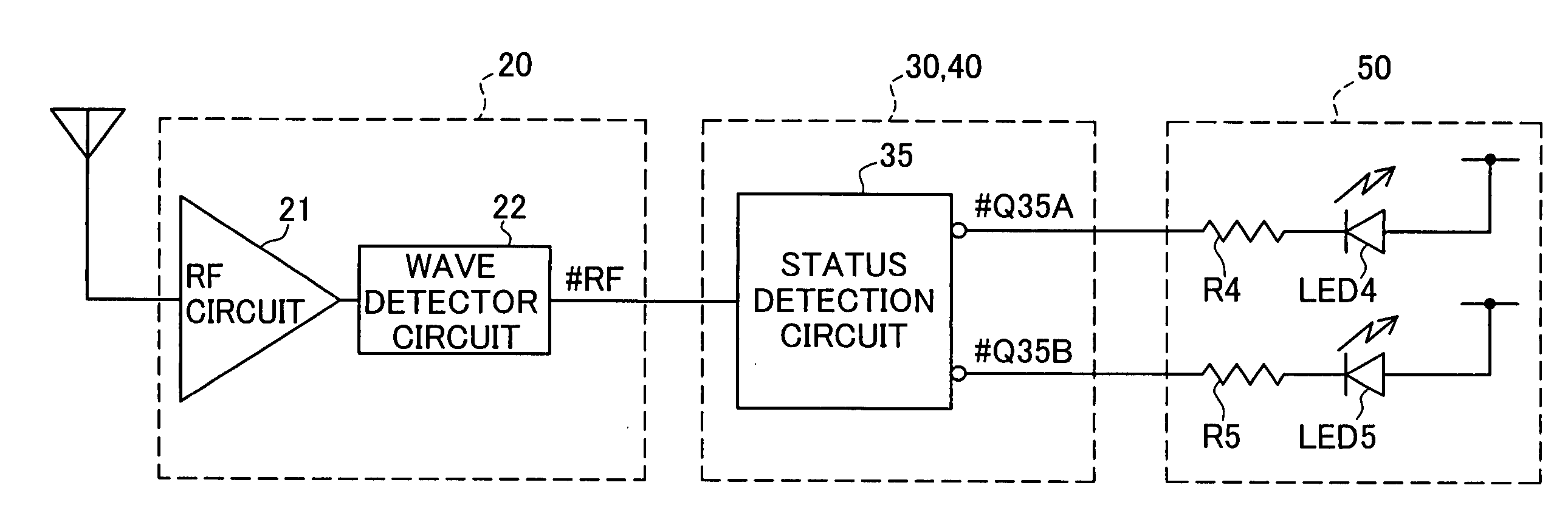
[0057] The status detection circuit 35 works as discussed below. FIG. 8 is a flowchart showing a processing routine executed by the status detection circuit 35 in the invention. When the program enters the processing routine shown in FIG. 8, the status detection circuit 35 first reads the detection output #RF from the wave detector circuit 22 of the wave detection module 20 and extracts a pattern of the detection output #RF (step S810). The status detection circuit 35 subsequently determines whether or not the extracted pattern coincides with an inherent pattern of a wireless LAN device (step S820). When the extracted pattern intermittently varies at a period of not greater than 500 ms, it is determined at step S820 that the extracted pattern coincides with the inherent pattern of the wireless LAN device. The status detection circuit 35 then sets the negative logic output #Q35A to the level L and the negative logic output #Q35B to the level H (step S830). The program then exits from...


PUM


Abstract

In a detector device 10 of the invention, a wave detection module 20 receives and detects radio wave in a predetermined frequency band, which is used by a target wireless communication device for telecommunication. An extraction module 30 extracts a pattern representing a time-series variation in presence or absence of the detected radio wave. An identification module 40 compares the extracted pattern with inherent patterns of radio wave transmitted from plural devices, which use the radio wave in the predetermined frequency band and include the target wireless communication device, and thereby identifies the propagation environment of the radio wave transmitted from the target wireless communication device. A display module 50 displays a result of the identification by changing lighting statuses of LEDs. When smooth telecommunication of a wireless communication device is interrupted, this arrangement of the invention desirably identifies the reason of the interrupted communication.

Description

BACKGROUND OF THE INVENTION [0001] 1. Field of the Invention [0002] The present invention relates to a technique of detecting the propagation environment of radio wave used for wireless telecommunications by a wireless communication device. [0003] 2. Description of the Related Art [0004] Wireless local area networks (hereafter may be referred to as wireless LANs) and cell phone systems are typical examples of wireless telecommunication that utilizes radio wave for transmission of information. A known technique applied to a terminal device of telecommunication detects the propagation status of radio wave used for telecommunication, based on the intensity of an electric field of radio wave signals between a base station and a terminal device. [0005] The terminal device that detects the propagation status of radio wave used for telecommunication based on the intensity of the electric field of radio wave signals between the base station and a terminal device is disclosed, for example, i...

Claims


Application Information

Patent Timeline
IPC IPC(8): H04B1/18H04B17/23H04B1/10H04B17/00H04B17/345H04L12/28H04W24/00H04W84/12
CPCH04B1/1027H04W84/12H04W24/00H04B17/00
Inventor ISHIDOSHIRO, TAKASHISONOBE, YOSHIIKU
Owner BUFFALO CORP LTD
Why Eureka
Try Eureka