Dynamic load fixture for application of torsion loads for rotary mechanical systems

Active Publication Date: 2006-04-06
RAYTHEON CO
View PDF8 Cites 25 Cited by
  • Summary
  • Abstract
  • Description
  • Claims
  • Application Information

AI Technical Summary

Benefits of technology

[0008] The present invention provides a dynamic load fixture (DLF) for applying a dynamic torsion load to a rotary mechanical system to achieve the demanding aerodynamic load exposures encountered by a CAS in flight. Real-time control of a dynamic load that can be independent of the angular rotation of the CAS unit under test (UUT) allows the DLF to more effectively r

Problems solved by technology

Conventional servo controllers such as PID feedback although adeq

Method used


Image

  • Dynamic load fixture for application of torsion loads for rotary mechanical systems
  • Dynamic load fixture for application of torsion loads for rotary mechanical systems
  • Dynamic load fixture for application of torsion loads for rotary mechanical systems

Examples


Example

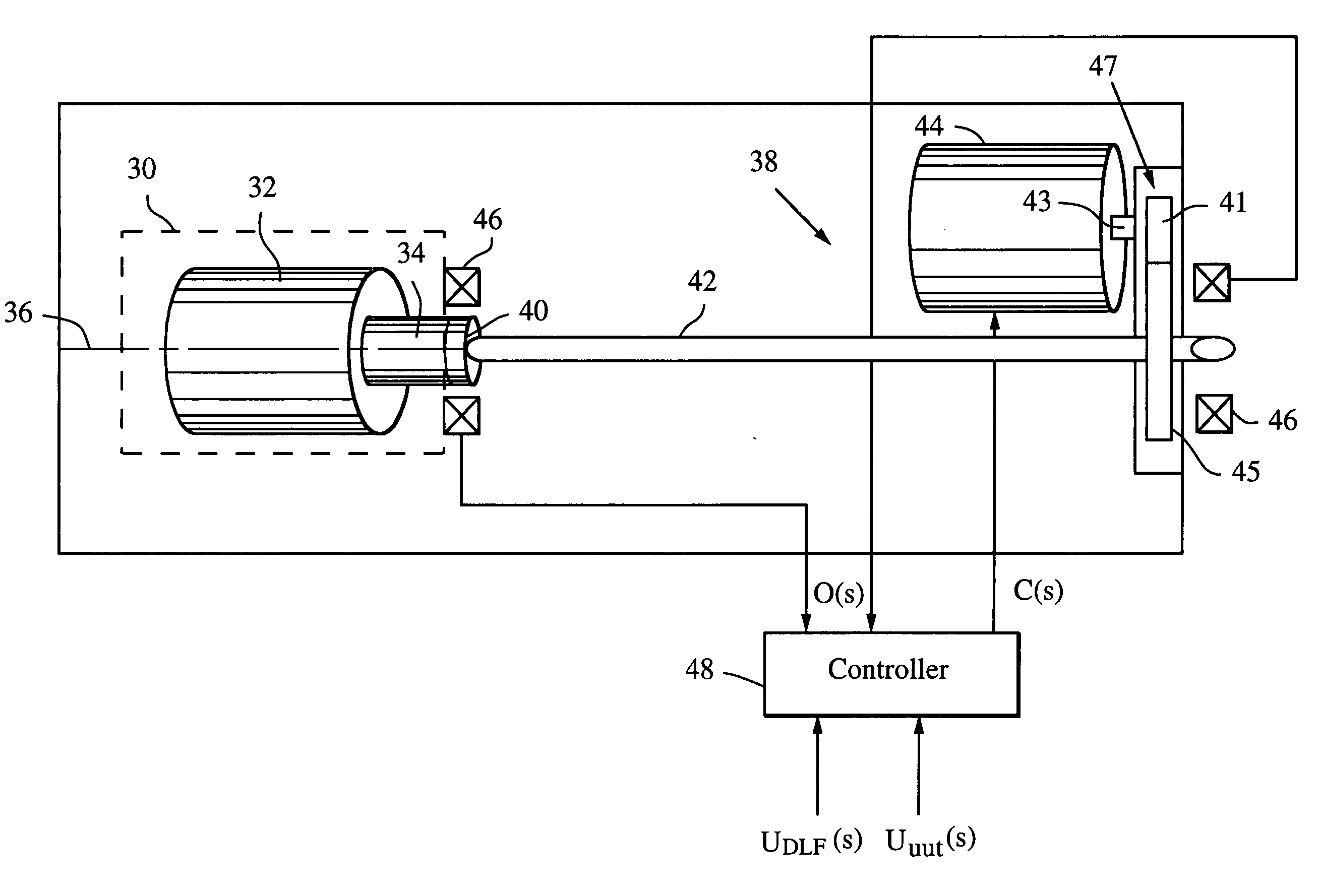
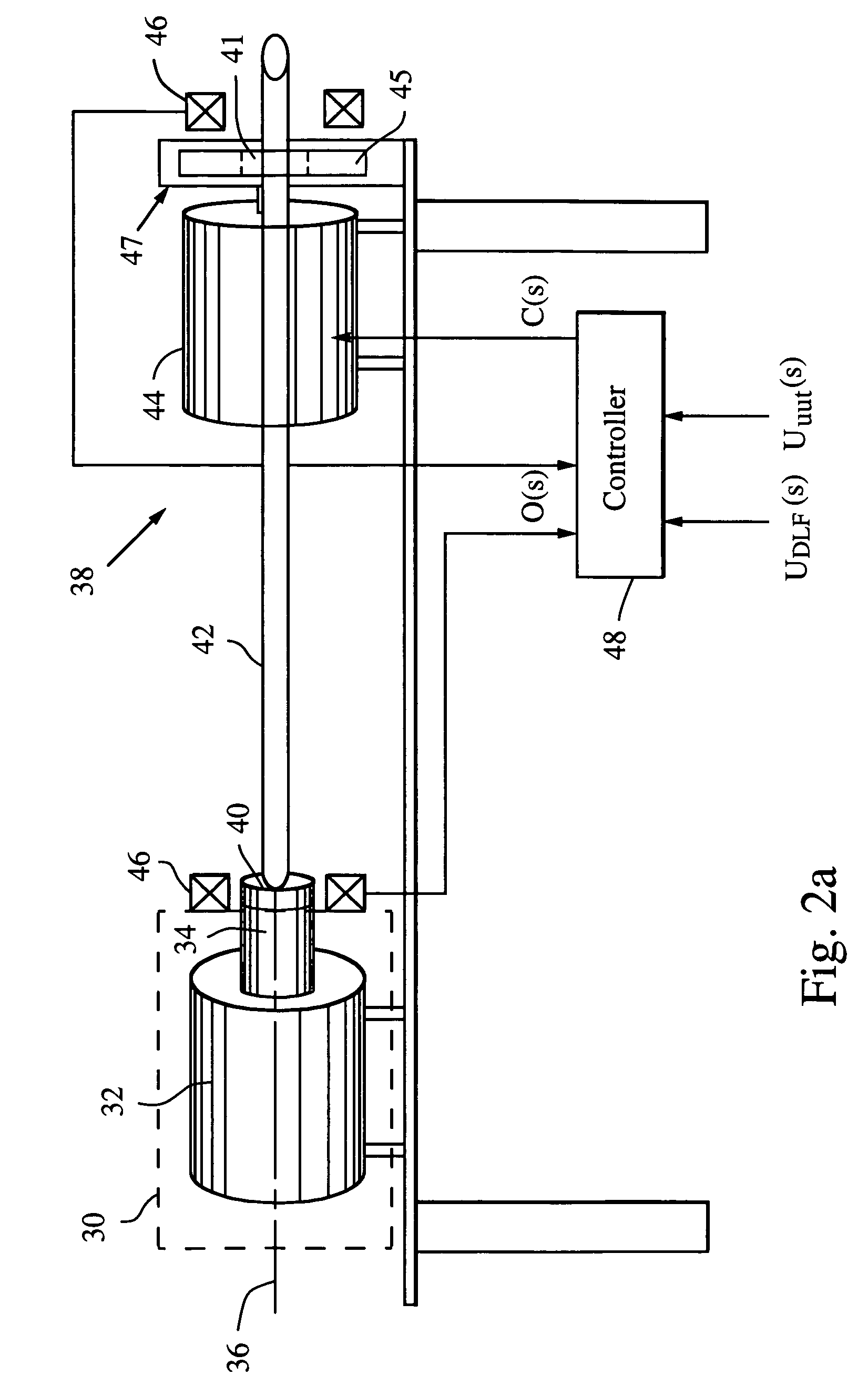
[0024] The present invention provides a dynamic load fixture (DLF) for applying a dynamic torsion load to a rotary mechanical system to achieve the demanding aerodynamic load exposures encountered by a control actuation system (CAS) in flight. Instead of fixing the end of the torsion bar, the DLF controls the application of torque to the torsion bar, hence the UUT via a DLF motor. Consequently the dynamic load can be independent of the angular rotation of the CAS unit under test (UUT), which allows the DLF to more effectively reproduce desired acceptance tests such as torque-at-rate and nonlinear loads. To provide the high response bandwidth needed to effectively test the UUT, the DLF employs classical phase lead or modern state space control, which is suitably augmented with a priori characterization information of the UUT. The DLF is particularly well suited for rotary mechanical systems that exhibit a limited range of motion and high frequency content such as control actuation sy...


PUM


Abstract

A dynamic load fixture (DLF) applies a torsion load to a unit under test (UUT) to achieve the demanding aerodynamic load exposures encountered by a control actuation system (CAS) in flight. Instead of fixing the end of the torsion bar, the DLF controls the application of torque to the torsion bar, hence the UUT via a DLF motor. The dynamic load can be independent of the angular rotation of the UUT, which allows the DLF to more effectively reproduce desired acceptance tests such as torque-at-rate and nonlinear loads. Furthermore, application of the loads through a torsion bar allows the system the compliance needed to generate precise loads while allowing for the flexibility of changing torsion bars to test a wide variety of UUT on one test platform. To achieve the demanding aerodynamic load exposures encountered by a CAS in flight, the controller must be able to respond both very fast and very precisely. Control is enhanced by the thorough characterization of the DLF and application of either “classic” negative feedback control or “modern” state-space control methods of linear observers and quadratic optimum control.

Description

BACKGROUND OF THE INVENTION [0001] 1. Field of the Invention [0002] This invention relates to test fixtures for applying loads to a rotary mechanical system and more specifically to dynamic load fixtures for applying a controllable torsion load capable of replicating acceptance test procedures and nonlinear load conditions. [0003] 2. Description of the Related Art [0004] The use of rotary mechanical systems to power automobiles, drive robotics, actuate flight control systems on airplanes and missiles and many other mechanical systems is ubiquitous throughout our economy. The use of a motor to rotate a shaft to actuate these various systems is a cost effective and reliable way to convert electrical energy into a mechanical force. In many applications such as found in an automobile, the motor rotates the drive shaft at a high and relatively constant rate. Therefore, the shaft has a large range of motion but a relatively small frequency content. In other applications such as found in a...

Claims


Application Information

Patent Timeline
IPC IPC(8): G01N3/22
CPCB64F5/0045G01M13/025G01N3/22B64F5/60
Inventor DE LAIR, CHARLES M.CLINE, R. BRIANOWAN, CHRISTOPHER P.CROFT, DONALD E.STILSON, SHANE P.
Owner RAYTHEON CO
Why Eureka
Try Eureka