
Bulldozer autograding system

a bulldozer and autograding technology, applied in the field of bulldozers, can solve the problems of a talented driver, uneven and rough terrain where the bulldozer starts working, and a large amount of skill

Active Publication Date: 2006-04-06
BLUE LEAF I P INC
View PDF45 Cites 31 Cited by
  • Summary
  • Abstract
  • Description
  • Claims
  • Application Information

AI Technical Summary

Benefits of technology

[0015] In accordance with a third aspect of the invention, a computer-implemented method of controlling the pitching of a bulldozer blade during movement over the ground is provided, the method including the steps of (1) reading a blade actual position that indicates an actual position of the bulldozer blade; (2) comparing the blade actual position signal with a blade target position signal; (3) determining a hydraulic valve signal that is calculated to drive the blade from the actual position to the target position; and (4) driving the blade to the target position. The step of comparing may include the step of calcula...

Problems solved by technology

Often the terrain that the bulldozer starts working is quite uneven and rough.
This ability to anticipate the motion of the chassis and pitch the blade in the opposite direction takes a good deal of skill, and that skill can only be acquired through experience.
Even a talented driver, however, cannot travel at full speed over rough terrain, but must reduce his speed to accommodate the pitching of the dozer blade as the dozer chassis pitches up and down as it travels over the ground.
This system, however, requires the careful placement and adjustment of light sources and an unobstructed view of the bulldozer blade.
What the inventors have discovered is that for many applications this laser-guided whole-field system is overkill.

Method used


Image

  • Bulldozer autograding system
  • Bulldozer autograding system
  • Bulldozer autograding system

Examples


Embodiment Construction

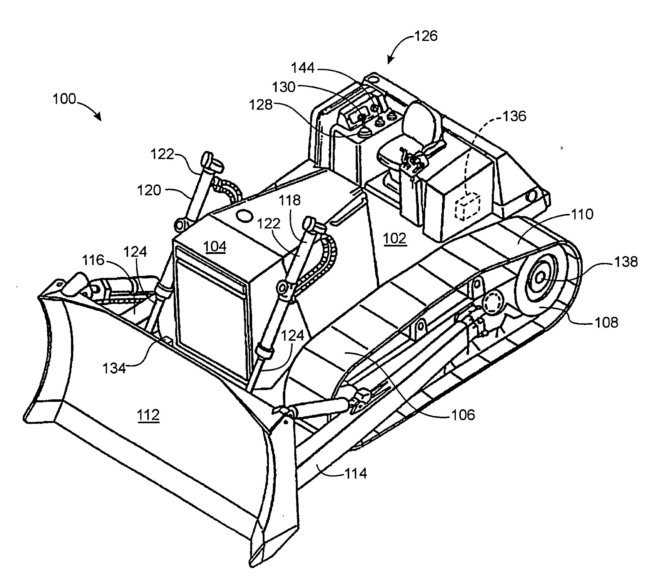
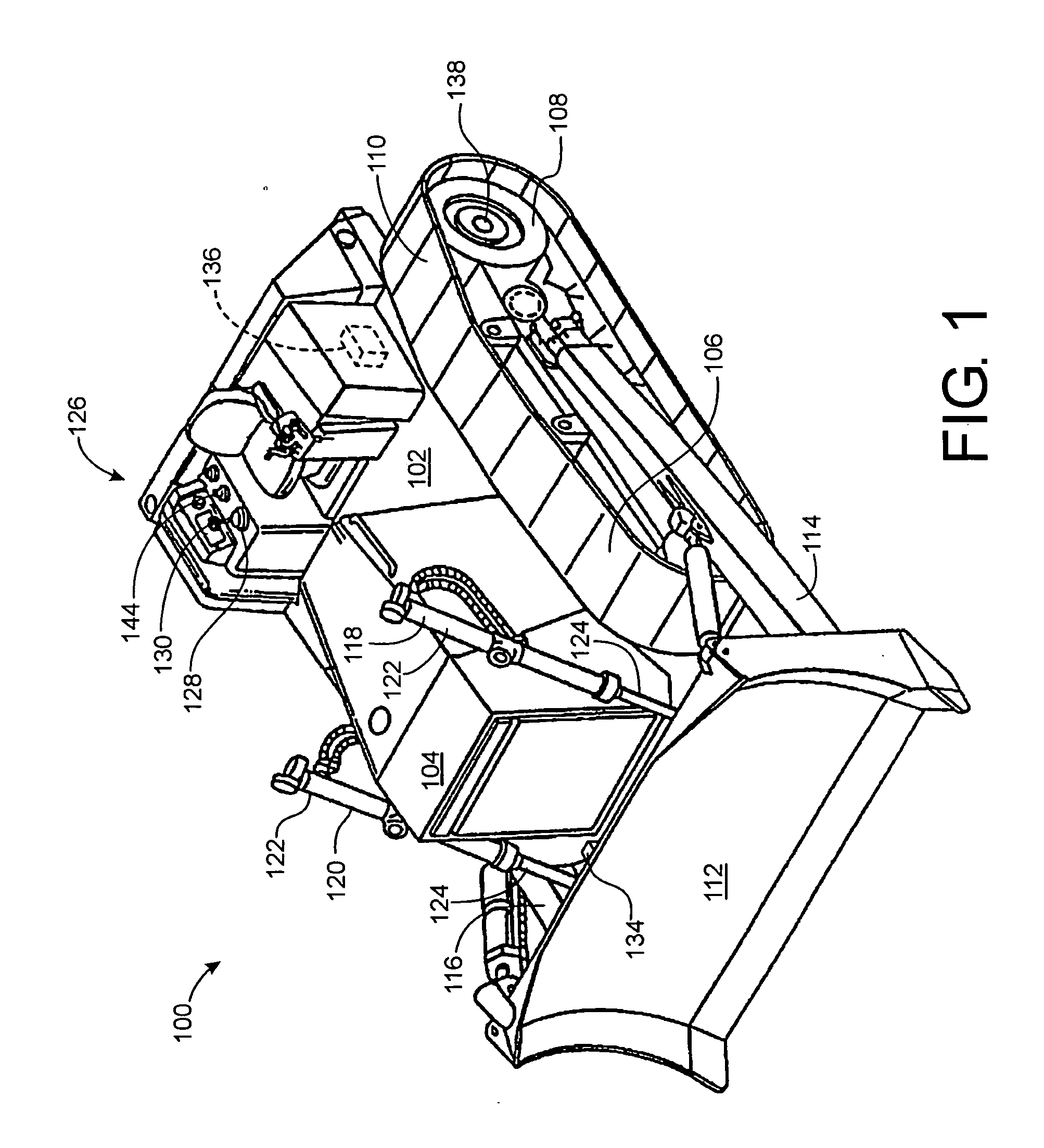
[0020]“Dozer” or “bulldozer” as used herein refers to a crawler-tractor coupled to a blade. “Crawler-tractor” refers to any of the class of work vehicles having a chassis, with an engine and ground-engaging endless-loop tracks that are disposed on either side of the chassis, that are driven by the engine, and that move the chassis over the ground.

[0021]“Blade position” and “blade height” are used in the discussion below to refer to the position or height of the blade with respect to the ground on which the bulldozer is supported and the angle of the blade with respect to the chassis and with respect to the horizon. If the crawler-tractor chassis pitches forward, lowering the front of the chassis closer to the ground, the automatic pitch control system disclosed herein raises the blade with respect to the dropping front of the dozer to maintain a relatively constant blade height with respect to the ground. If the chassis pitches backward, raising the front of the chassis, the system...


PUM


Abstract

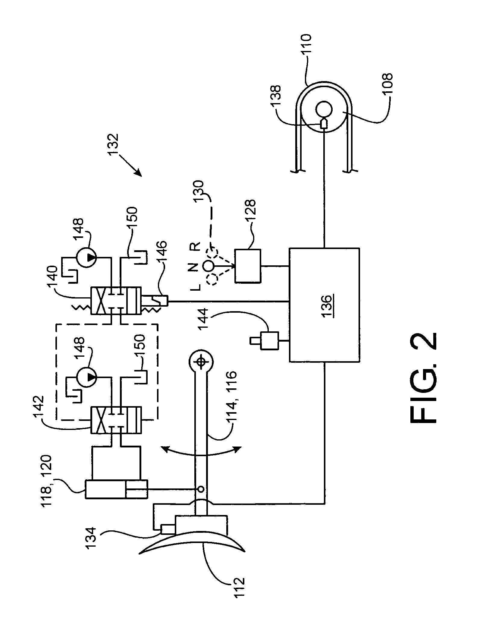
A dozer blade control system controls the position of a bulldozer blade, maintaining the blade at a constant position as the dozer travels through a worksite. The control system monitors the angle of the dozer blade with respect to the earth and when it senses that the dozer blade is tilting, it corrects the dozer blade's position by extending or retracting hydraulic cylinders that couple the dozer blade to the chassis of the crawler-tractor. When the dozer chassis pitches forwards, the blade begins to tilt forward and to drop closer to the ground. The control system senses this forward rotation of the blade and retracts the hydraulic cylinders that couple the blade to the chassis, causing the blade to return to and maintain its original position. Conversely, when the dozer chassis pitches backwards and the blade begins to tilt backward and rise higher above the ground, the control system extends the hydraulic cylinders coupling the blade to the chassis and lowers the blade, causing the blade to return to and maintain its original position with respect to the earth.

Description

FIELD OF THE INVENTION [0001] The invention relates generally to bulldozers. More particularly, it relates to systems for keeping the blade of a bulldozer at a selected position as the bulldozer is operated. BACKGROUND OF THE INVENTION [0002]“Bulldozers” or “dozers”, as those terms are used herein, refer to crawler-tractors that are equipped with a blade for scraping the ground or pushing material along the ground. The blade is pivotally connected to the crawler-tractor chassis such that they can pivot up and down. Blade controls are provided to the operator in the cab of the vehicle. These controls permit the operator raise and lower the blade with respect to the chassis of the crawler-tractor. One of the most common uses for blades on bulldozers is to level or otherwise contour ground for construction of houses, buildings, parking lots, and roads. Often the terrain that the bulldozer starts working is quite uneven and rough. As it passes over this rough terrain, the bulldozer chas...

Claims


Application Information

Patent Timeline
IPC IPC(8): A01B41/06
CPCE02F3/844E02F3/845
Inventor LUMPKINS, GEORGE T.DIX, PETER J.SHORE, DANIEL B.
Owner BLUE LEAF I P INC
Learn More