
Device and method for manufacturing a stator of an electrical machine

a technology of electrical machines and stators, which is applied in the manufacture of dynamo-electric machines, dynamo-electric machines, electrical apparatus, etc., can solve the problems of increasing the cost-effectiveness of realization, and achieve the effects of improving the power density of the machine, increasing the copper factor, and easy and economical manufacturing

Inactive Publication Date: 2006-04-06
BOSCH REXROTH AG
View PDF2 Cites 8 Cited by
  • Summary
  • Abstract
  • Description
  • Claims
  • Application Information

AI Technical Summary

Benefits of technology

"The present invention provides a new way to design and manufacture electrical machines with poles that are easy to install and have a high copper factor. The poles are made up of a rib and a head, with a front recess extending along the entire length of the pole. The front recess is symmetrical and extends along the entire length of the pole. The pole has a T-shaped cross section with a rib and a head, and the head can be mounted on the rib using a form-fit connection. This simplifies the installation process and allows for additional copper to be added to the winding spaces. The invention also provides a simplified method for manufacturing the electrical machine with identically-configured poles. Overall, the invention improves the performance and cost-effectiveness of electrical machines."

Problems solved by technology

In addition, cost-effectiveness of the realization is increased.

Method used


Image

  • Device and method for manufacturing a stator of an electrical machine
  • Device and method for manufacturing a stator of an electrical machine
  • Device and method for manufacturing a stator of an electrical machine

Examples


Embodiment Construction

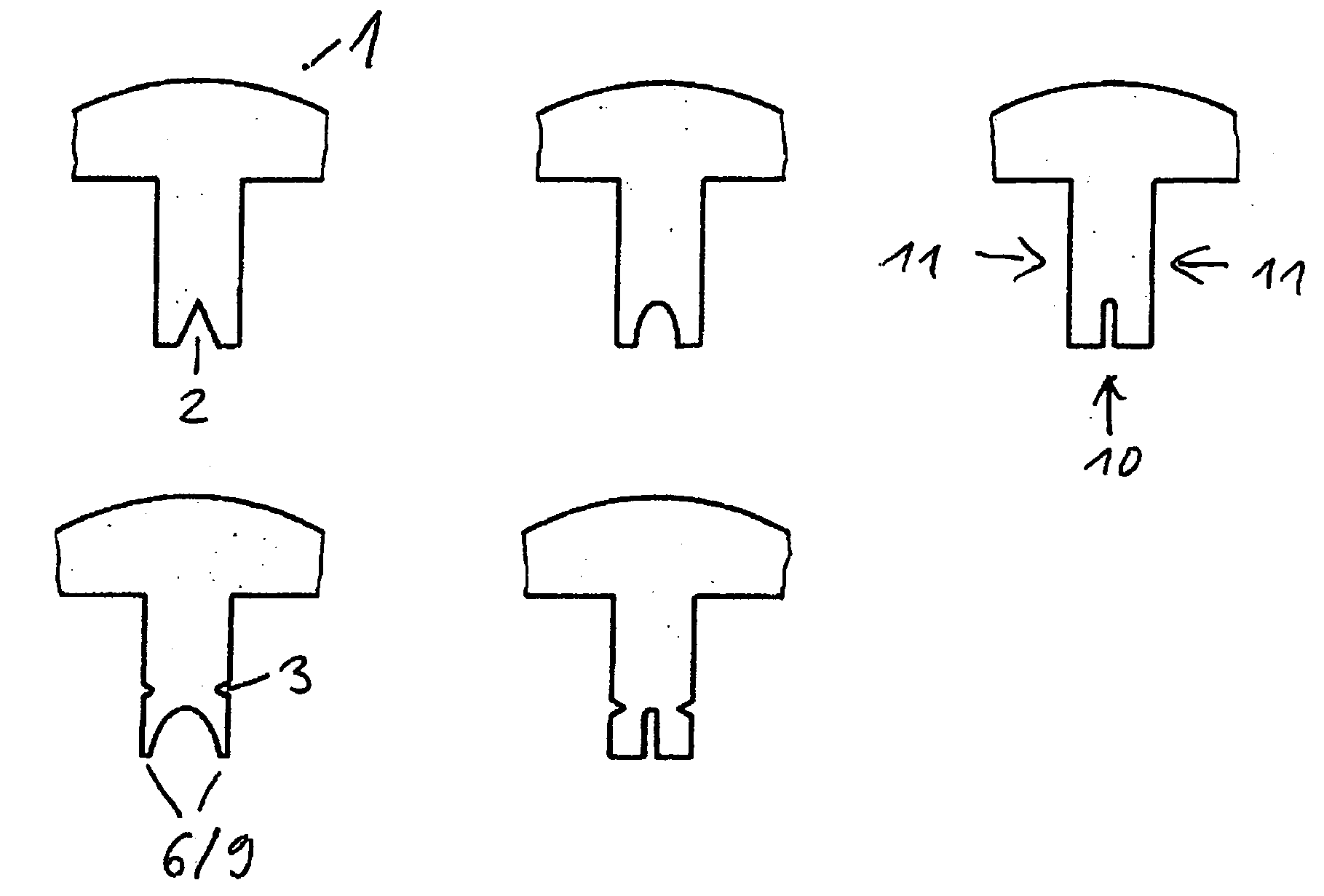
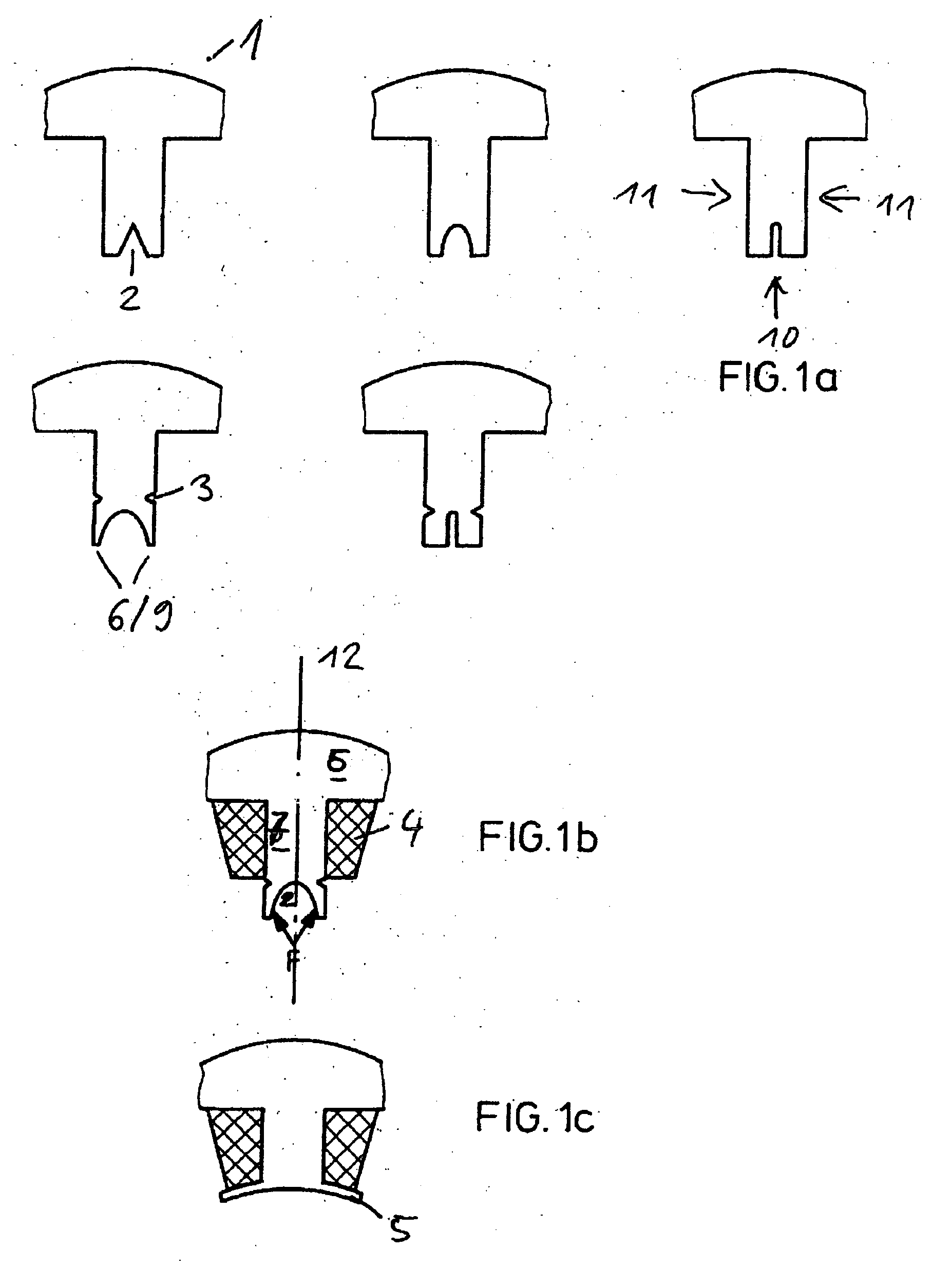
[0028] Single-component crude part 1 in FIG. 1a includes a head part 6, a rib 7 and a groove 2 formed along the longitudinal axis of rib 7. Groove 2 is located on front side 10 of rib 7 diametrically opposed to head part 6, as mirror images relative to the axis of symmetry. This groove can be configured in the shape of a V or U, and be more or less wide. Other advantageous groove profiles are also feasible and are within the ability of one skilled in the art. As an option, a further groove 3 is shown on lateral surface 11 of rib 7, which can also be configured in the shape of a V or a U. Groove 3 is equidistant from head 6 on both sides, and is located at the level of the base of front-side groove 2, extending parallel thereto. Groove 3 extends along the entire length of the crude part and serves to simplify the bending of leg 9, since the material that would have to be compressed during bending is not even there.

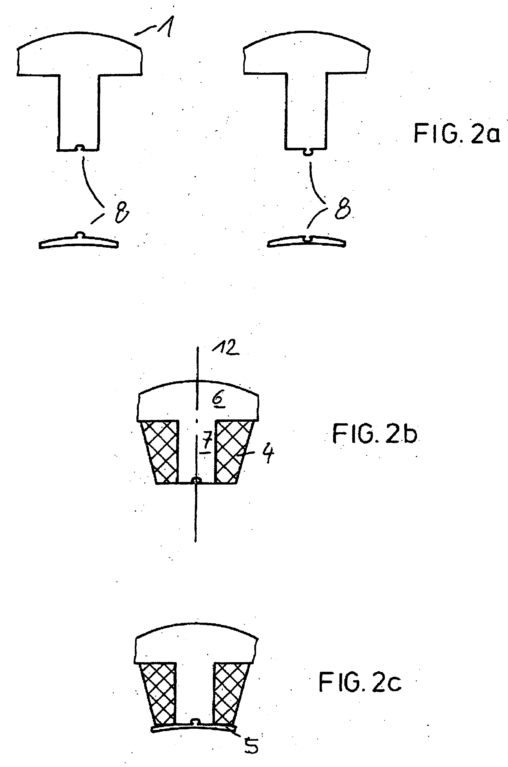
[0029] A crude part 1 with a winding 4 installed on rib 7 is shown in...


PUM

PropertyMeasurementUnit
symmetryaaaaaaaaaa
lengthaaaaaaaaaa
mechanical tensionaaaaaaaaaa

Abstract

A component for an electrical machine has a body having a T-shaped cross section including rib and a head, and a front side located diametrically opposite to the head and oriented parallel to the latter, and also provided with a front recess which is substantially symmetrical around an axis of symmetry and extends longitudinally.

Description

BACKGROUND OF THE INVENTION [0001] The present invention is based on the general class of dynamoelectrical machines and describes various embodiments of machine components and a method for manufacturing machines of this type according to the definitions of the species in the independent claims. [0002] Numerous devices and methods are known from the related art that make it possible to manufacture an electrical machine using individual components. Typically, the stator ring of an inner or outer rotor is first assembled out of individual components and then secured using an outer guide, e.g., a support tube. [0003] Unexamined patent application DE 101 19 642 A1 discloses a stator ring with a yoke having an external hexagon shape and an annular inner shape, the stator ring being composed of a core with longitudinal recesses and windings located thereon on the inside, the windings being placed on separate, removable winding carriers. The configuration includes wound poles and non-wound ...

Claims


Application Information

Patent Timeline
Patent Type & Authority Applications(United States)
IPC IPC(8): H02K3/48H02K15/14
CPCH02K1/146Y10T29/49009H02K15/022
Inventor GROENING, INGOLFHAHN, INGOKUNKEL, HELMUTBACH, JOACHIM
Owner BOSCH REXROTH AG
Learn More