Injection molding machine

a molding machine and injection molding technology, applied in the direction of molding tools, couplings, fluid couplings, etc., can solve the problems of increasing the initial cost, increasing the overall cost, so as to reduce the overall initial cost

Active Publication Date: 2011-03-01
NISSEI PLASTIC IND CO LTD
View PDF39 Cites 3 Cited by
  • Summary
  • Abstract
  • Description
  • Claims
  • Application Information

AI Technical Summary

Benefits of technology

[0009]An objective of the present invention is to provide an injection molding machine that can eliminate the use of a large-sized drive motor, corresponding to the maximum capacity of the injection molding machine, even if the injection molding machine is large in size, that can reduce the overall initial cost including the servo circuit, for example, even when a servomotor is used as a drive motor.
[0010]Another objective of the present invention is to provide an injection molding machine where control is stabilized and moldability and molding quality are improved. At the same time, avoiding or reducing occurrence of overload enables improving the reliability and realization of longevity.
[0011]Another objective of the present invention is to provide an injection molding machine where a separate measure against an unstable region, where the number of revolutions of the drive motor becomes small, is unnecessary or reduceable, enabling improved energy savings and reduced running cost.

Problems solved by technology

First, when the injection molding machine is large in size, since a large servomotor is required in response to the maximum capacity of the injection molding machine, the servomotor itself becomes expensive, increasing the initial cost. Because the upsizing of the servomotor creates a larger capacity (greater electric current) for an auxiliary servo circuit (servo amplifier), ensuring resistance to electric power in the servo circuit and results in the gradual increase of the overall cost.
Secondly, since all operations in the injection molding machine is controlled by one servomotor, a region where the operation capability of the servomotor does not conform to each operational process of the injection molding machine easily occurs. Therefore, control tends to be unstable, which is disadvantageous from the standpoint of securing moldability and molding quality. At the same time, since the overload frequency becomes greater, which is disadvantageous from the standpoint of reliability and longevity, as well. In addition, as a measure against unstable regions where the number of revolutions of the servomotor becomes smaller, when the hydraulic oil to be discharged from the hydraulic pumps is relieved to the oil tank, if one unit of a large-sized servomotor is used, the energy waste becomes great, which is also disadvantageous from the standpoint of energy savings and running costs.

Method used


Image

  • Injection molding machine
  • Injection molding machine
  • Injection molding machine

Examples


Embodiment Construction

[0023]Next, a preferred embodiment relating to the present invention is described in detailed based upon the drawings. Furthermore, the attached drawings do not specify the present invention, but are for the purpose of more easily understanding of the present invention. Regarding well-known portions, in order to prevent the invention from becoming ambiguous, detailed descriptions are omitted.

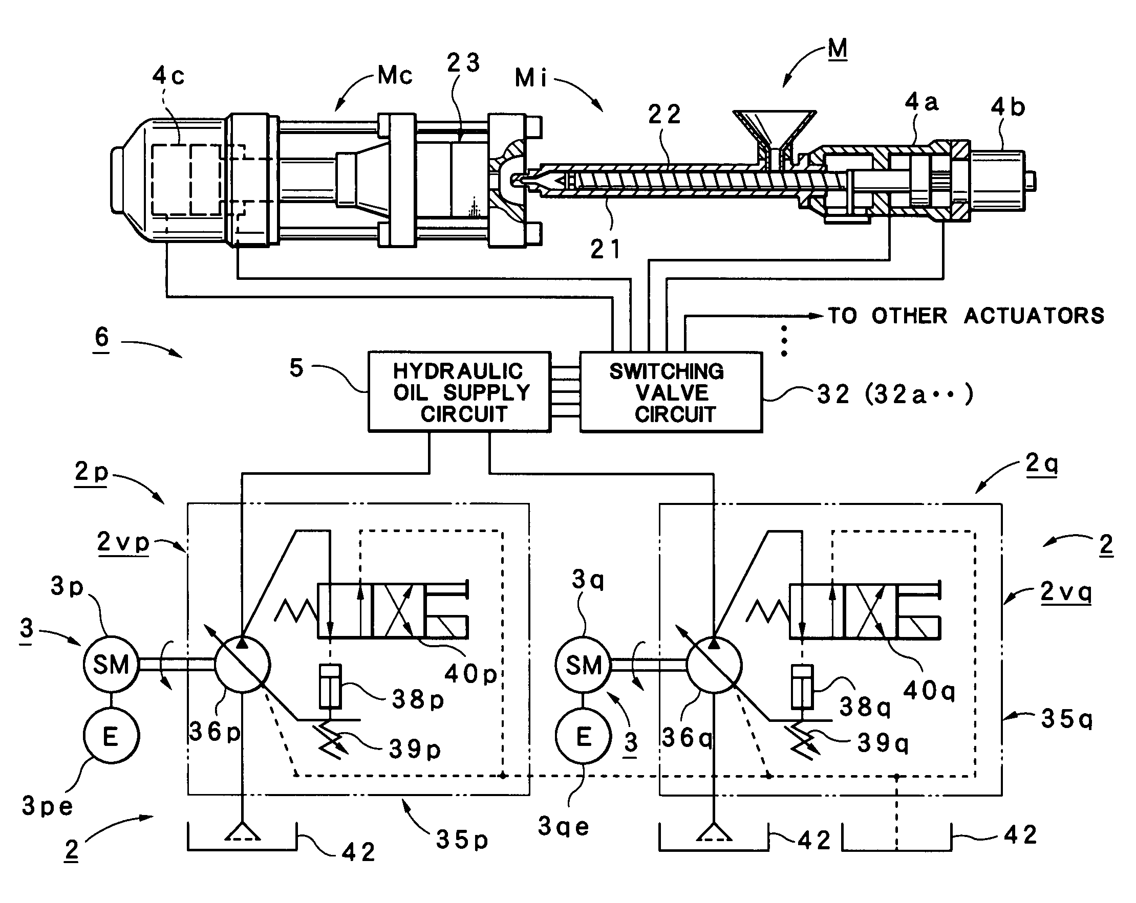
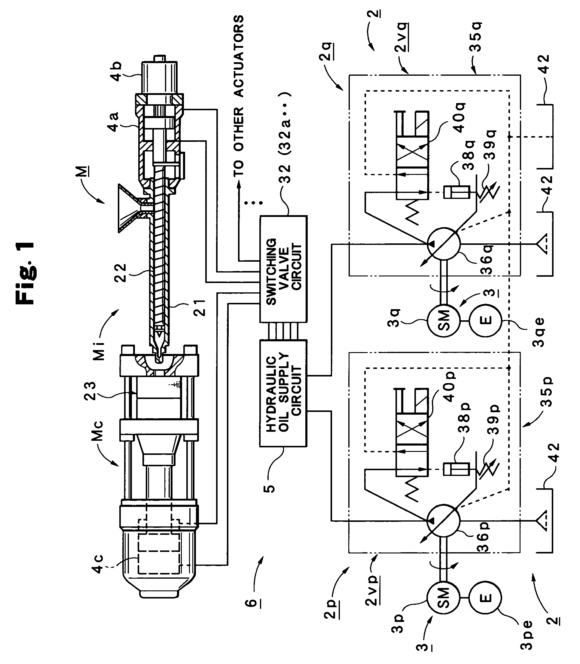
[0024]First, an entire construction of an injection molding machine M relating to this embodiment is described with reference to FIG. 1 to FIG. 4.

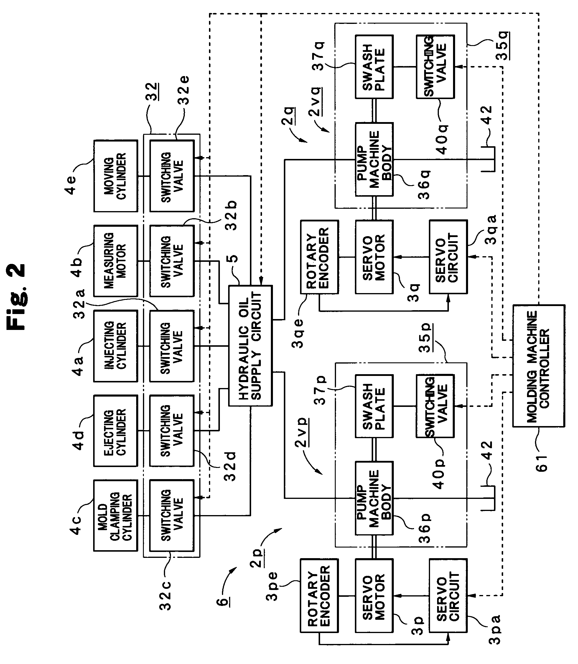
[0025]In FIG. 1, M is an injection molding machine, equipped with an injection unit Mi and a mold clamping device Mc. The injection molding machine M is equipped with an injecting cylinder 4a that moves a screw 22, which is internally contained in a heating cylinder 21 of the injection unit Mi, back and forth, and a measuring motor (oil motor) 4b that rotates the screw 22; At the same time, it is equipped with a mold clamping cylinder 4c that opens / clo...


PUM

PropertyMeasurementUnit
discharge flow ratesaaaaaaaaaa
discharge flow rateaaaaaaaaaa
stabilityaaaaaaaaaa

Abstract

When constructing an injection molding machine M that is equipped with hydraulic pumps 2, which control discharge flow rates by variably controlling the number of revolutions of a drive motor 3, and that drives hydraulic actuators 4a . . . by these hydraulic pumps 2; the injection molding machine M is equipped with a hydraulic drive member 6 having multiple hydraulic pumps 2p and 2q, and a hydraulic oil supply circuit 5 jointly or individually supplying hydraulic oil to be discharged from multiple hydraulic pumps 2p and 2q to a hydraulic actuator 4a, 4b, 4c, 4d or 4e selected from the multiple hydraulic actuators 4a . . . .

Description

BACKGROUND OF THE INVENTION[0001]1. Field of the Invention[0002]The present invention relates to an injection molding machine driving hydraulic actuators by hydraulic pumps, which control discharge flow rates by variably controlling the number of revolutions of a drive motor.[0003]2. Description of the Relevant Art[0004]Conventionally, an injection molding machine that is equipped with a hydraulic pump controlling a discharge flow rate by variably controlling the number of revolutions of a drive motor, and that drives a hydraulic actuator, such as an injecting cylinder (hydraulic cylinder), by the hydraulic pump is known in Japanese Patent Publication No. 3245707.[0005]The objective of the injection molding machine disclosed in the publication is to improve the stability of pressure control by eliminating the fluctuation of the controlled pressure at the time of pressure control, and [the injection molding machine] is equipped with a hydraulic drive source controlling the number of ...

Claims


Application Information

Patent Timeline
Patent Type & Authority Patents(United States)
IPC IPC(8): B29C45/77
CPCB29C45/82
Inventor YAMAURA, HIROSHIUNNO, YOSHIMOTO
Owner NISSEI PLASTIC IND CO LTD
Why Eureka
Try Eureka