Lens holder for lens device and process of assembring lens device equipped with the lens holder

a lens device and lens holder technology, applied in the field of optical lens devices, can solve the problems of deterioration in molding accuracy, increase in molding cost, and difficulty in molding lens mounting members and cam followers with high accuracy, and achieve the effect of improving the optical performance of the lens device, low cost, and high accuracy

Inactive Publication Date: 2006-01-12
FUJI PHOTO OPTICAL CO LTD
View PDF6 Cites 19 Cited by
  • Summary
  • Abstract
  • Description
  • Claims
  • Application Information

AI Technical Summary

Benefits of technology

[0010] According to the lens holder for a lens device that comprises the lens mounting frame for fixedly mounting a lens or a lens group therein and the union collar with cam followers prepared separately eliminates the use of slide molds for formation of the lens holder, realizes high accuracy, low cost lens holders and easily improves optical performance of the lens device. Further, since the union collar is provided commonly to lens holders for a plurality of lenses or lens groups, it is realized to reduce initial cost. Furthermore, in the case where a lens group has high sensitivity on its optical design, the separate structure of the lens holder enables eccentricity adjustment between the lens mounting frame and the union collar, so that fine optical axis alignment of the lens device is accomplished. This leads to enhanced image quality. Coupling of the lens mounting frame and the union collar is easily achieved by press-fitting, a simple structure of coupling means, adhesion bond or set screws.
[0011] Since the assembling process comprises the steps of assembling the union collars into a cam barrel and, thereafter, fixedly coupling the lens mounting frames to the union collars together, the union collar is assembled to the cam barrel with high accuracy, so that the lens mounting frame and the cam barrel are coupled with increased accuracy. The use of the fixture upon assembling a plurality of the union collars to the cam barrel enables easy positional adjustment between the cam barrel and the union collars and between the union collars themselves.

Problems solved by technology

Since the injection molding with slide molds encounters not only deterioration in molding accuracy, it has been hard to mold a lens mounting member and cam followers of the lens holder with high accuracy but also an increase in molding cost.

Method used


Image

  • Lens holder for lens device and process of assembring lens device equipped with the lens holder
  • Lens holder for lens device and process of assembring lens device equipped with the lens holder
  • Lens holder for lens device and process of assembring lens device equipped with the lens holder

Examples


Embodiment Construction

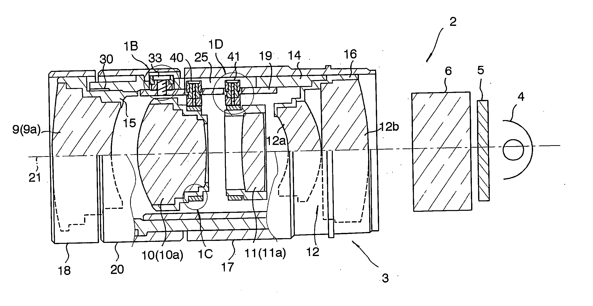
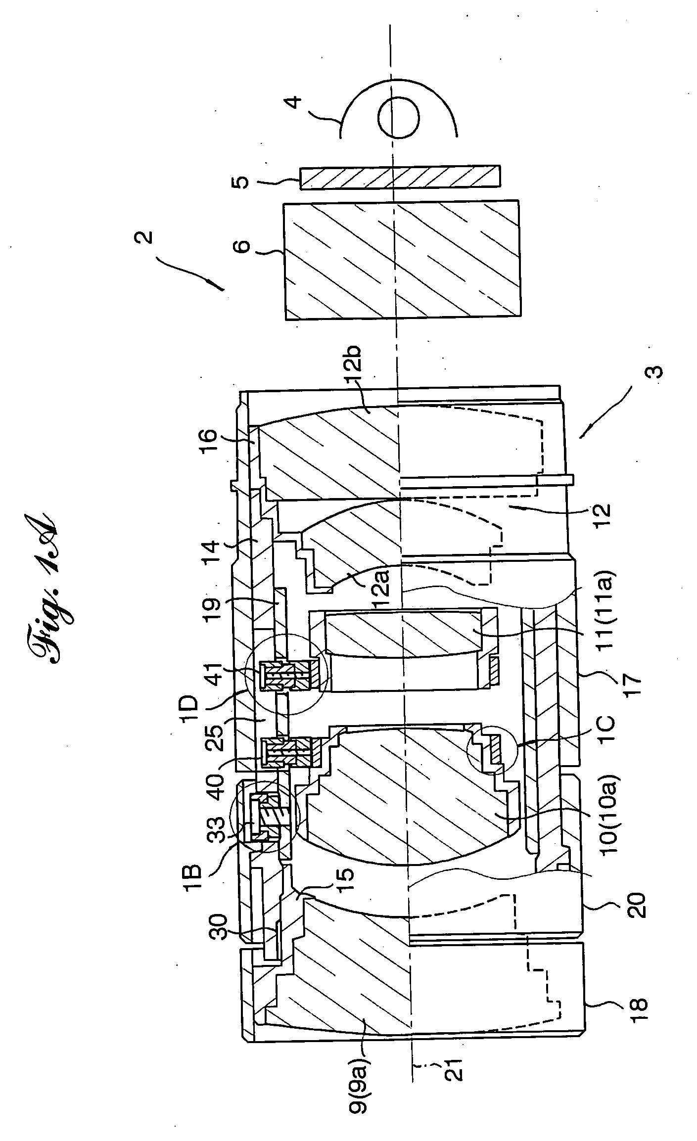
[0026] Referring to the accompanying drawings in detail, and in particular, to FIGS. 1A through 1D showing an image projection unit 2 of a projector (not shown), the image projection init 2 comprises a zoom lens 3, a dichroic prism 4, a transmission image display 5 such as a liquid crystal display (LCD), and a projection lamp 6. Light emanating from the projection lamp 5 filters out the transmission image display 5 and impinges on the dichroic prism 4. Three primary color images (R, G and B images) displayed on the transmission image display 5 are combined as a color image by the dichroic prism and projected by the zoom lens 3 onto a screen remote from the projector. The zoom lens 3 has a zoom lens system comprising four lens groups, namely a first lens group 9 comprising a lens 9a that that is operative as a front converter or focusing lens, a second lens group 10 comprising a lens 10a that is operative as a variater lens, a third lens group 11 comprising a lens 11a that is operati...


PUM


Abstract

A lens device includes a plurality of lens groups, a lens holder for holding each lens group, a cam barrel for receiving the lens holder therein so as to allow axial movement of the lens holder, and a cam mechanism having cam slots formed in the cam barrel and cam followers provided on the lens holder in slide engagement with the cam slots, respectively, through which rotation of the cam barrel causes the axial movement of the lens holder. The lens holder includes a lens mounting frame for fixedly mounting the lens group therein; and a union collar fixedly coupled to the lens mounting frame; and the cam followers are fix to the union collar.

Description

BACKGROUND OF THE INVENTION [0001] 1. Field of the Invention [0002] The present invention relates to an optical lens device including a plurality of lens groups movably mounted in a cam barrel so as to move in an axial direction following rotation of the cam barrel, and, more particularly, to improvement of a structure of a lens holder for mounting a lens group in a cam barrel, and a process of assembling the lens device. [0003] 2. Description of Related Art [0004] Various types of zoom lenses are nowadays widely used for optical instruments such as photographic cameras and optical projectors. Such a zoom lens comprises an optical lens system consisting of a plurality of lens groups and lens barrels mounting the lens groups therein so as to cause relative movement of the lens groups in an axial direction for focusing and zooming by rotating one or more lens barrels. Each lens group consisting of one or more optical lens elements is fixedly held in a lens holder provided with a plura...

Claims


Application Information

Patent Timeline
Patent Type & Authority Applications(United States)
IPC IPC(8): G02B7/02
CPCG02B7/10
Inventor SAKAMOTO, KENICHIMASUZAWA, TOMONARI
Owner FUJI PHOTO OPTICAL CO LTD
Why Eureka
Try Eureka