
Method and apparatus for providing lens aberration compensation by illumination source optimization

a technology of illumination source and compensation method, applied in the field of photolithography, can solve the problems of reducing the size of an integrated circuit, reducing cd (critical dimension) of the corresponding mask pattern approaching the resolution limit of the optical exposure tool, so as to prolong the useful life of the projection lens, improve imaging performance, and improve pattern fidelity

Active Publication Date: 2006-04-25
ASML NETHERLANDS BV
View PDF16 Cites 5 Cited by
  • Summary
  • Abstract
  • Description
  • Claims
  • Application Information

AI Technical Summary

Benefits of technology

[0023]The method of the present invention provides important advantages over the prior art. Most importantly, the present invention provides a lithographic source pattern optimization tool that automatically determines an illumination shape that compensates for lens aberrations and allows users to image with higher pattern fidelity. As a result, the present invention results in improved imaging performance and extends the useful life of the projection lens. As the projection lens is typically one of the most expensive parts of the imaging system, it is a significant benefit to extend the life of the projection lens (i.e., by improving the performance of the lens and compensating for degradations in lens performance over time, the present invention minimizes the frequency with which the lens need to be replaced). In addition, the method of the present invention also allows for the simultaneous optimization of additional metrics, such as, but not limited to, exposure latitude “EL”.

Problems solved by technology

These rules are set by processing and design limitations.
As the size of an integrated circuit is reduced and its density increases, however, the CD (critical dimension) of its corresponding mask pattern approaches the resolution limit of the optical exposure tool.
One factor that degrades the overall performance of the lithographic process is aberrations in the projection lens.
Indeed, even though current manufacturing processes allow for production of lenses having high quality standards, lens aberrations still exist, which degrade the imaging performance.
Furthermore, lenses age over time, and can exhibit an increase in aberrations and / or flare, thereby further degrading the performance of the lens.
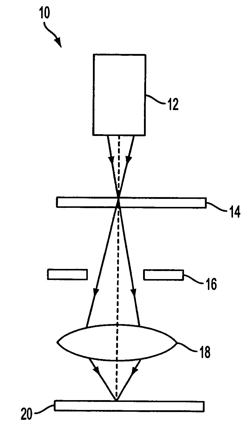
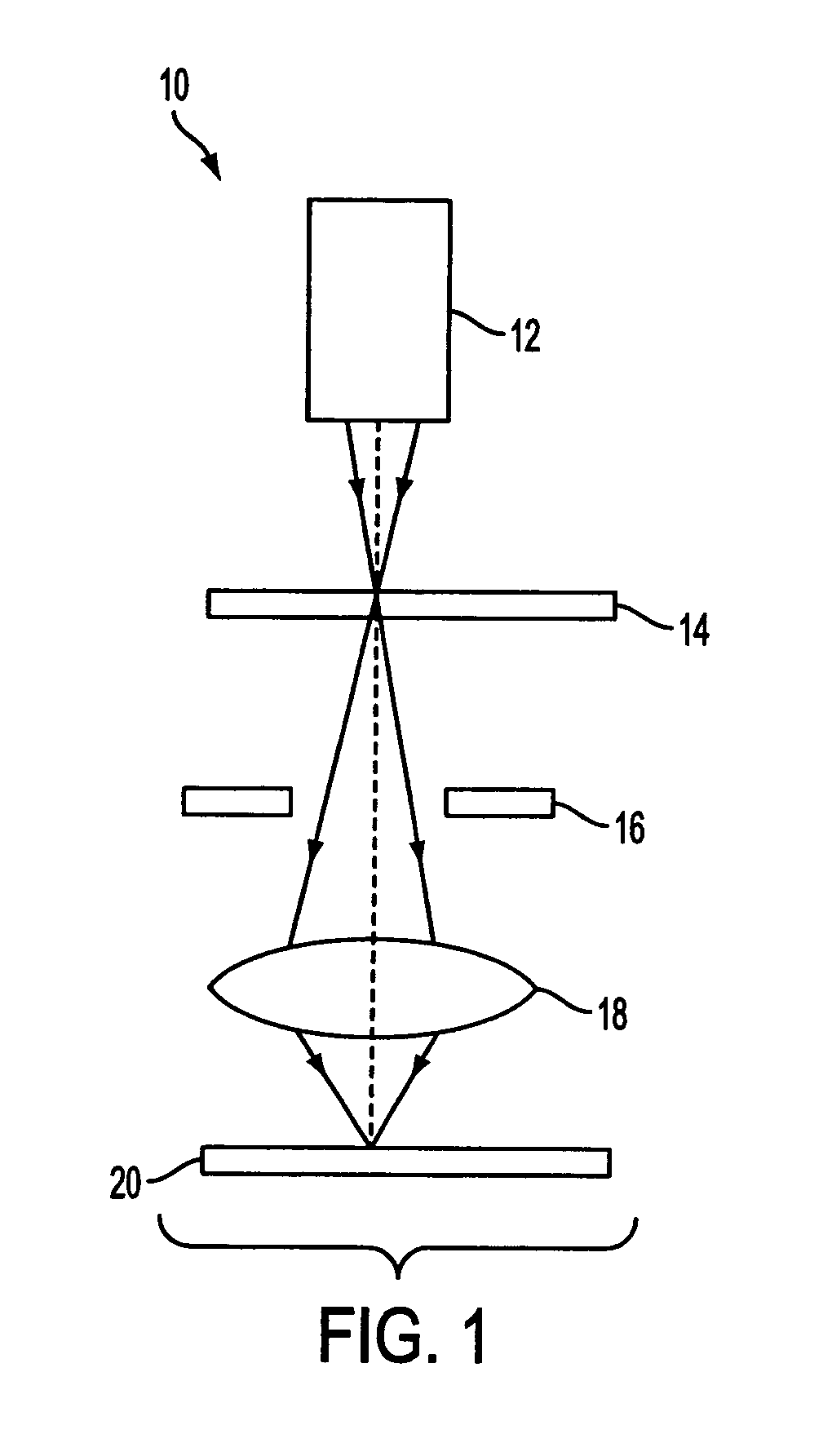
As can be appreciated from FIG. 1, if aberrations exist in the projection lens of the imaging system, degradations in performance occur.
However, while maximizing the aerial image log-slope at selected sampling locations in the pattern enhances the budget / tolerance for exposure variations, commonly referred to as the exposure latitude (EL), it does not help to increase the budget / tolerance for focus variations, commonly referred to as the depth of focus (DOF).
Thus, the optimization routine of Rosenbluth would suffer from this problem.
A further limitation of the optimization process of Rosenbluth is that the effect of a diffraction pattern on the projected image is assumed to be independent of the position of the diffraction orders in the pupil plane.
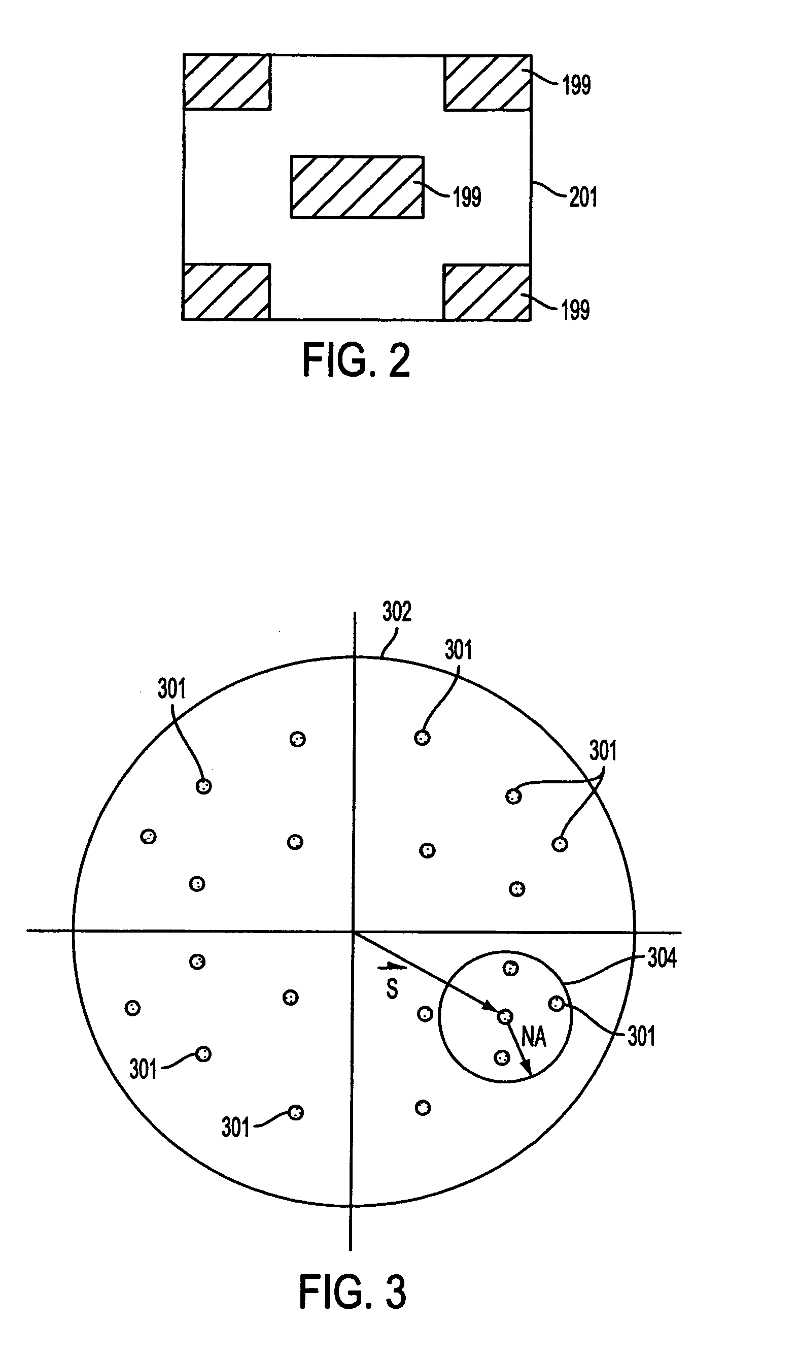
However, such illuminators have predetermined shapes that may or may not produce the optimal possible illumination profile.
Currently, there is no method for optimizing such source shape patterns to account for lens aberrations in the projection lens, while also improving both the DOF and the EL for a given lithographic process.

Method used


Image

  • Method and apparatus for providing lens aberration compensation by illumination source optimization
  • Method and apparatus for providing lens aberration compensation by illumination source optimization
  • Method and apparatus for providing lens aberration compensation by illumination source optimization

Examples


Embodiment Construction

[0033]As explained in further detail below, the object of the lithographic optimization process of the present invention is to first define and then minimize a cost metric “C” under a varying set of imaging conditions, where the cost metric C is a function of a set of process parameters which returns a numeric value that quantifies the performance of the imaging system. Importantly, the cost metric C must reflect the effects of lens aberration on imaging perform. In accordance with the present invention, the cost metric quantifies the effect of the shape of the illumination source on the resulting image printed on the substrate. The smaller the cost metric, the better the imaging process will perform (i.e., the more accurately the resulting image matches the target pattern).

[0034]As a practical matter, lithographic process optimization involves satisfying multiple constraints. Examples of such constraints include, but are not limited to, maximizing the image log slope, maximizing th...


PUM

PropertyMeasurementUnit
wavelengthaaaaaaaaaa

Abstract

A method for compensating for lens aberrations, which includes the steps of: (a) defining a cost metric which quantifies an imaging performance of an imaging system, where the cost metric reflects the effects of lens aberrations on the imaging performance; (b) defining a source illumination profile; (c) evaluating the cost metric based on the source illumination profile; (d) modifying the source illumination profile, and re-evaluating the cost metric based on the modified source illumination profile; and (e) repeating step (d) until the cost metric is minimized. The source illumination profile corresponding to the minimized cost metric represents the optimal illumination for the imaging device.

Description

[0001]This application claims the benefit of 60 / 425,309, filed Nov. 12, 2002.FIELD OF THE INVENTION[0002]The present invention relates to photolithography, and in particular relates to a method for providing improved performance of lithographic processes by compensating for lens aberrations by performing an illumination source optimization process. In addition, the present invention relates to a device manufacturing method which incorporates the optimization process and utilizes a lithographic apparatus comprising a radiation system for providing a projection beam of radiation; a mask table for holding a mask, serving to pattern the projection beam; a substrate table for holding a substrate; and a projection system for projecting the patterned projection beam onto a target portion of the substrate.BACKGROUND OF THE INVENTION[0003]Lithographic projection apparatus (tools) can be used, for example, in the manufacture of integrated circuits (ICs). In such a case, the mask contains a ci...

Claims


Application Information

Patent Timeline
Patent Type & Authority Patents(United States)
IPC IPC(8): G03B27/68G03B27/52H01L21/027G03F7/20
CPCG03F7/705G03F7/70125H01L21/027
Inventor LIEBCHEN, ARMIN
Owner ASML NETHERLANDS BV
Learn More