Electro-optical devices using dynamic reconfiguration of effective electrode structures

US20110109824A1Active Publication Date: 2011-05-12POINT FINANCIAL

Image

  • Electro-optical devices using dynamic reconfiguration of effective electrode structures
  • Electro-optical devices using dynamic reconfiguration of effective electrode structures
  • Electro-optical devices using dynamic reconfiguration of effective electrode structures

Examples


Embodiment Construction

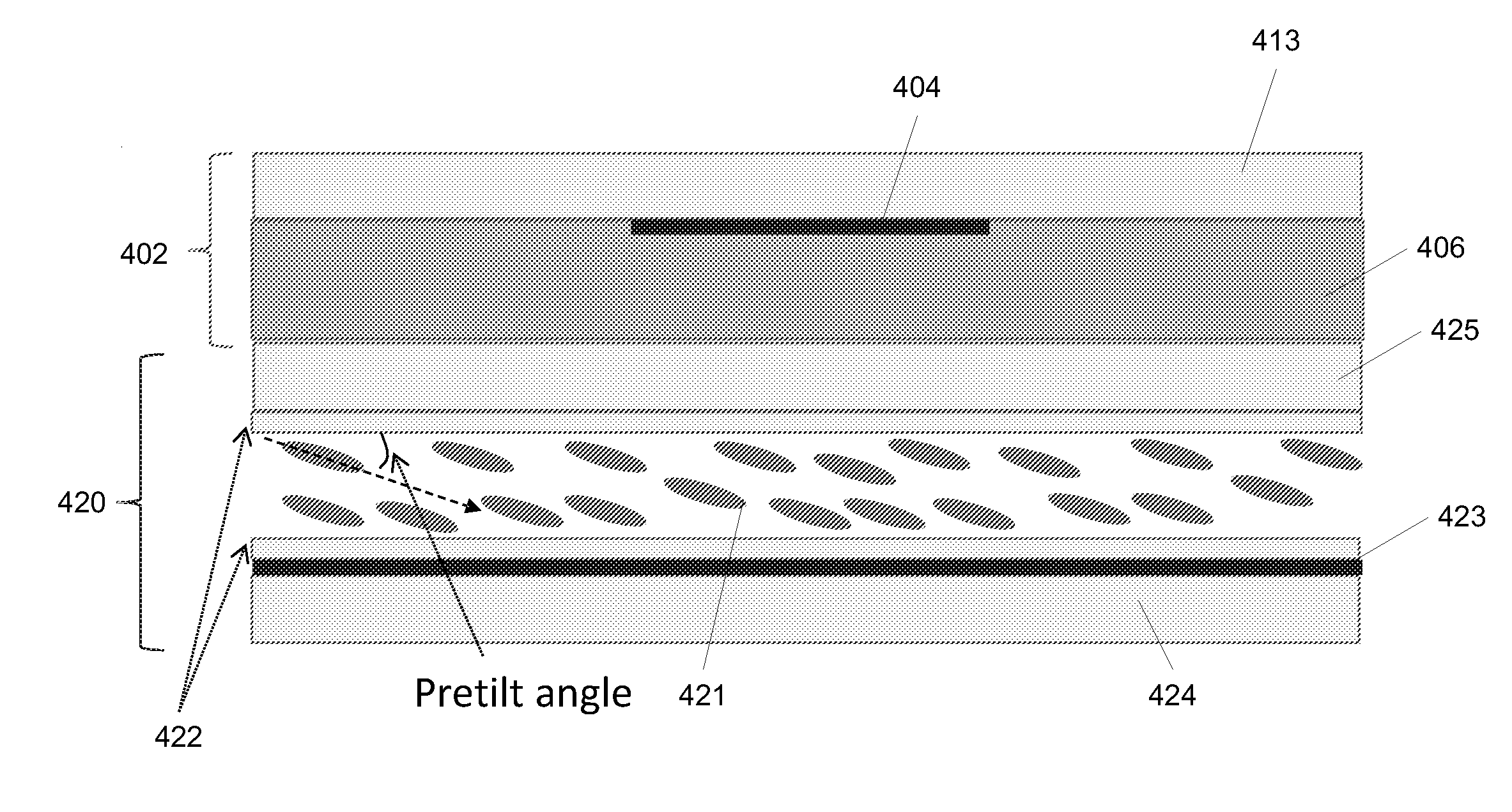
[0077]The present invention is directed to a tunable liquid crystal (LC) lens using a frequency dependent material to modify a spatial profile of the electric field via frequency tuning. Thus, tuning of the lens can be frequency controlled. The devices of the present invention may be used for tunable focusing, diffracting, steering, etc. The devices of the present invention may also be used for controlling a LC optical device that is fixed. FIG. 4A schematically illustrates a tunable LC lens using a layer 406 of a material having a frequency dependent characteristic. This material may be, for example, a high dielectric constant material, or a material of weak conductivity, and is hereinafter referred to, for brevity, as the “frequency dependent material.” Functionally, the material has the characteristic of allowing a limited degree of charge mobility through it, and that degree of charge mobility is dependent on the frequency of the electrical signal applied to the device. Thus, fo...


PUM


Abstract

Variable liquid crystal devices for controlling the propagation of light through a liquid crystal layer use a frequency dependent material to dynamically reconfigure effective electrode structures in the device. The frequency of a drive signal that generates an electric field in the device may be varied, and the frequency dependent material has different charge mobilities for the different frequencies. At a low charge mobility, the frequency dependent material has little effect on the existing electrode structures. However, at a high charge mobility, the frequency dependent material appears as an extension of the fixed electrodes, and may be used to change the effective electrode structure and, thereby, the spatial profile of the electric field. This, in turn, changes the optical properties of the liquid crystal, thus allowing the optical device to be frequency controllable.

Description

FIELD OF THE INVENTION[0001]This invention relates to the field of electrically tunable optical devices, particularly those using liquid crystal.BACKGROUND OF THE INVENTION[0002]Tunable liquid crystal (LC) optical devices, such as lenses, beam steering devices and shutters are known in the art. While some tunable LC lenses operate with a uniform electric or magnetic control field, most use a spatially modulated field. In the case of electric fields, there are a few prior art techniques used to spatially modulate the electric field. Spatially inhomogenous dielectric layers have been used to attenuate the electric field to have a desired spatial profile. Electrodes have been spherically shaped to provide a desired spatial profile to the electric field. Another approach to spatially modulating the electric field is to use a planar electrode whose impedance properties are such that the voltage drop over the electrode as AC drive current is fed to the electrode leads to a spatially modul...

Claims


Application Information

Patent Timeline
12 May 2011
Publication
US20110109824A1
IPC
G02F1/133; C09K19/52; H01B1/12; H01B3/20; G02F1/1343
CPC
C09K19/02; C09K19/52; G02F2001/294; G02F1/29; G02F1/13439; G02F1/294
Inventors
GALSTIAN, TIGRAN