Method and Apparatus for Pressure Swing Adsorption

a pressure swing adsorption and apparatus technology, applied in the direction of chemistry apparatus and processes, separation processes, dispersed particle separation, etc., can solve the problems of difficult recovery of highly valuable components, many unnecessary components in exhaust gas, etc., and achieve the effect of reducing the initial cost of the device, high recovery percentage, and reducing the cos

Active Publication Date: 2009-04-30
NIPPON SANSO CORP
View PDF22 Cites 21 Cited by
  • Summary
  • Abstract
  • Description
  • Claims
  • Application Information

AI Technical Summary

Benefits of technology

[0072]The PSA method of the present invention can recover the highly valuable target components in a high concentration with a high recovery percentage from the mixture gas discharged from the semiconductor manufacturing device, etc. Therefore, it is possible to reuse the atmospheric gas used in the semiconductor manufacturing device, etc. The cost can be significantly reduced. In addition, the initial cost for the device can be also reduced.
[0073]In particular, the strong adsorbate is led from the strong adsorbate high pressure storage tank as a product gas in the second PSA method of the present invention. Therefore, a product gas pressure required by the destination can be maintained without an additional compressor by fixing the appropriate amount in the strong adsorbate high pressure storage tank.

Problems solved by technology

However, many kinds of unnecessary components are often contained in the exhaust gas, as explained above.
Therefore, it is not easy to recover highly valuable components win a high concentration with a high recovery percentage.

Method used


Image

  • Method and Apparatus for Pressure Swing Adsorption
  • Method and Apparatus for Pressure Swing Adsorption
  • Method and Apparatus for Pressure Swing Adsorption

Examples


example 1

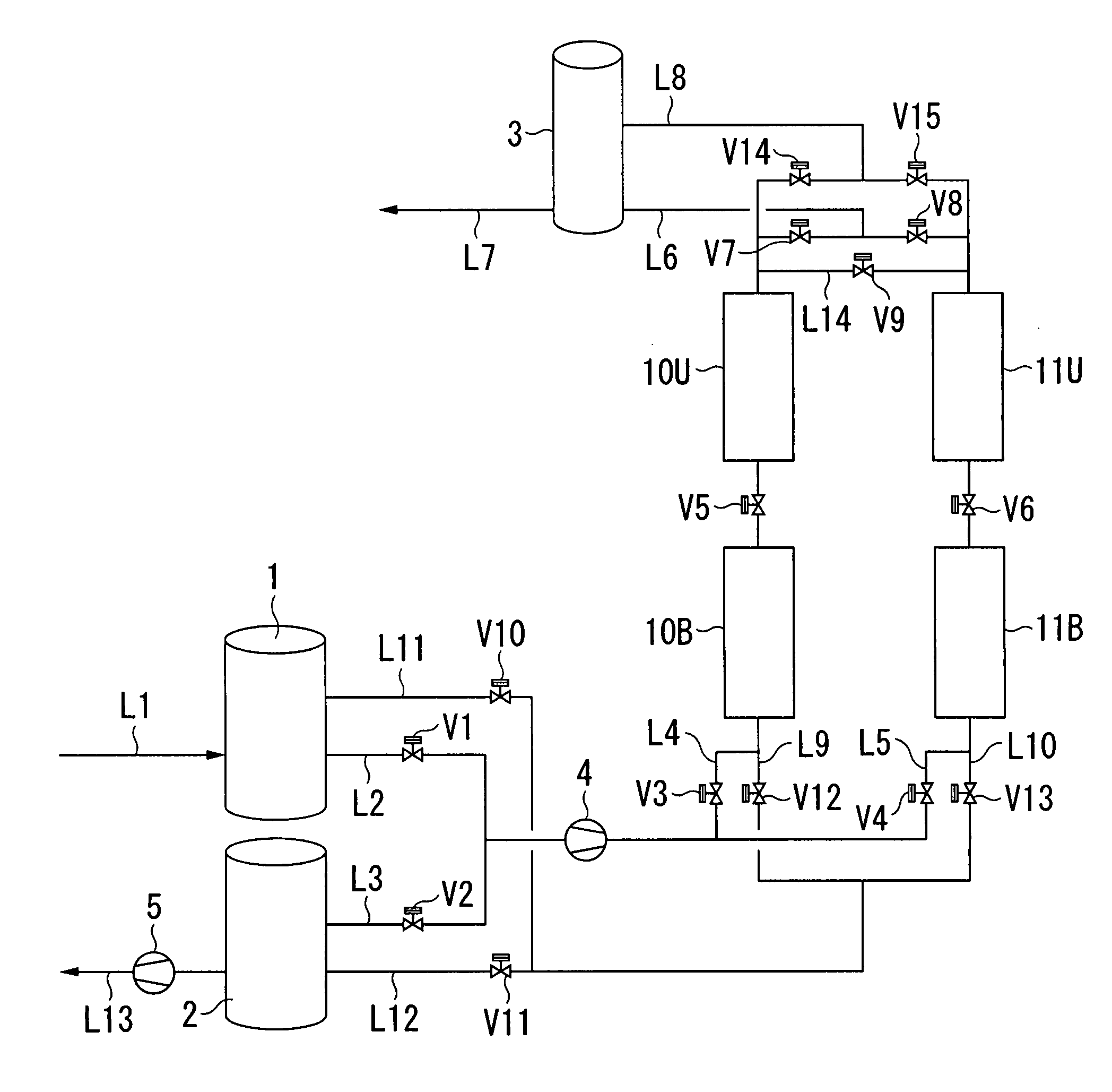
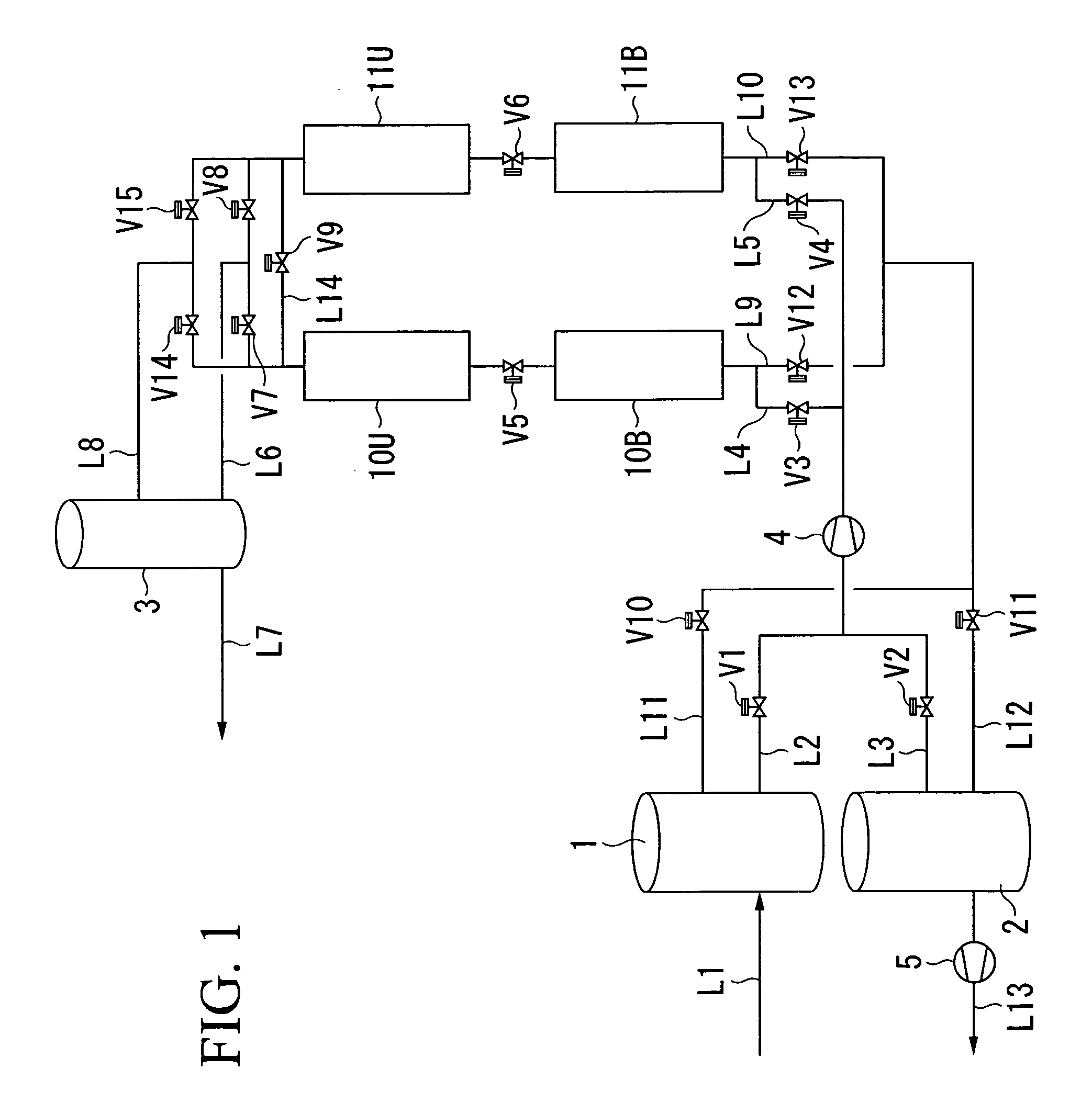
[0225]As Example 1, xenon was separated from a material gas containing xenon and nitrogen using the first PSA apparatus shown in FIG. 1.

[0226]As the lower columns 10B and 11B, and the upper columns 10U and 11U, a cylindrical container having an inner diameter of 108.3 mm and a height of 500 mm in which 2.0 kg of activated carbon was filled was used. The compressors 4 and 5 have a volume of 40 L / min and 20 L / min (the flow rate [L / min.] is a corresponding value under the conditions of 1 atom and 0° C.) respectively. The apparatus was operated such that the cycle time was 500 seconds, and the time in each step is shown in Table 7.

[0227]The flow rate of the material gas introduced into the material gas storage tank 1 was 2 L / min. The material gas composition was 50% by volume of xenon and 50% by volume of nitrogen. The flow rate of xenon recovered from the strong adsorbate storage tank 2 was 1 L / min. The flow rate of nitrogen recovered from the weak adsorbate storage tank 3 was 1 L / min....

example 2

[0230]As Example 2, xenon was separated from a material gas containing xenon, nitrogen, oxygen, argon, and hydrogen using the first PSA apparatus shown in FIG. 1.

[0231]The flow rate of the material gas introduced into the material gas storage tank 1 was 2.1 L / min. The material gas composition was 23.8% by volume of xenon, 23.8% by volume of nitrogen, 23.8% by volume of argon, 4.8% by volume of hydrogen, and oxygen as the remainder.

[0232]The flow rate of xenon recovered from the strong adsorbate storage tank 2 was 0.5 L / min. The flow rate of the mixture gas recovered from the weak adsorbate storage tank 3 was 1.6 L / min.

[0233]When the separation was continuously carried out for 24 hours under the same conditions as in Example 1 based on the time sequence shown in Table 7, the concentration of xenon contained in the mixture gas discharged from the line L7 was about 900 ppm, and the concentrations of nitrogen, oxygen, and argon contained in xenon discharged from the line L13 were all ab...

example 3

[0236]As Example 3, xenon was separated from a material gas containing xenon and nitrogen using the second PSA apparatus shown in FIG. 9.

[0237]As the lower columns 10B and 11B, and the upper columns 10U and 11U, a cylindrical container having an inner diameter of 83.1 mm and a height of 500 mm in which 1.5 kg of activated carbon was filled was used. The compressor 4 has a volume of 25 L / min (the flow rate [L / min.] is a corresponding value under the conditions of 1 atom and 0° C.). The strong adsorbate high pressure storage tank 25 has a volume of 2.5 L. The apparatus was operated such that the cycle time was 600 seconds, and the time in each step is shown in Table 6.

[0238]The flow rate of the material gas introduced into the material gas storage tank 1 was 3 L / min. The material gas composition was 10% by volume of xenon and 90% by volume of nitrogen. The flow rate of xenon recovered from the strong adsorbate high pressure storage tank 25 was 0.3 L / min. The flow rate of nitrogen reco...


PUM

PropertyMeasurementUnit
pore diameteraaaaaaaaaa
timeaaaaaaaaaa
heightaaaaaaaaaa

Abstract

In order to provide a new PSA method which can concentrate simultaneously a strong adsorbate such as xenon and a weak adsorbate such as nitrogen in a high concentration with a high recovery percentage when highly valuable gas such as xenon and krypton contained in the exhaust gas from a semiconductor manufacturing equipment, etc. is recovered in a high concentration with a high recovery percentage, the present invention provides a new PSA method in which the method uses a separation apparatus comprising a lower column and a upper column which are filled with an adsorbent, a material gas storage tank for storing the material gas to be introduced into the lower column, a strong adsorbate storage tank for storing a main component which is easily adsorbed by the adsorbent, and a compressor, and the strong adsorbate which is easily adsorbed by the adsorbent and the weak adsorbate which is not readily adsorbed by the adsorbent are recovered, wherein the method comprises an (a) adsorption step, (b) rinse step, (c) low column depressurization step, (d) upper column depressurization step, and (e) purge step sequentially repeated based on a predetermined sequence.

Description

TECHNICAL FIELD[0001]The present invention relates to a method and an apparatus for recovering highly valuable gas, such as krypton and xenon, from a gas mixture containing highly valuable gas in a high concentration with a high recovery percentage. Specifically, the present invention relates to a method and an apparatus for pressure swing adsorption which recovers highly valuable gas from exhaust gas discharged from semiconductor manufacturing equipment, such as a plasma sputtering device, a plasma oxidation device, a plasma nitridation device, a plasma CVD device, and a reactive ion etching device, and manufacturing equipment for display device (liquid crystal display etc.).[0002]Priority is claimed on Japanese Patent Application No. 2005-328582, filed Nov. 14, 2005, the content of which is incorporated herein by reference.BACKGROUND ART[0003]In the manufacturing for semiconductor products, such as semiconductor integrated circuits, liquid crystal panels, solar battery panels, and...

Claims


Application Information

Patent Timeline
Patent Type & Authority Applications(United States)
IPC IPC(8): B01D53/047
CPCB01D53/0423C01B2210/0082B01D53/053B01D2253/102B01D2253/108B01D2256/10B01D2256/12B01D2256/18B01D2257/11B01D2258/0216B01D2259/40054B01D2259/40079B01D2259/40081B01D2259/402B01D2259/41C01B23/0063C01B23/0068C01B2210/0035C01B2210/0037C01B2210/0042C01B2210/0045C01B2210/0046C01B2210/0053B01D53/0446B01D53/047C01B23/00
Inventor URAKAMI, TATSUSHI
Owner NIPPON SANSO CORP
Why Eureka
Try Eureka