
Electronic toll collection system

a technology of electronic toll collection and electronic toll collection, which is applied in the direction of burglar alarm mechanical actuation, burglar alarm by hand-portable articles removal, instruments, etc., can solve the problems of license plate transponder not being well adapted to communications with overhead gantry than windshield transponder, license plate transponder may encounter multipath problems, and signal cancellation at certain mountings

Active Publication Date: 2006-04-06
MARK IV INDS
View PDF53 Cites 53 Cited by
  • Summary
  • Abstract
  • Description
  • Claims
  • Application Information

AI Technical Summary

Benefits of technology

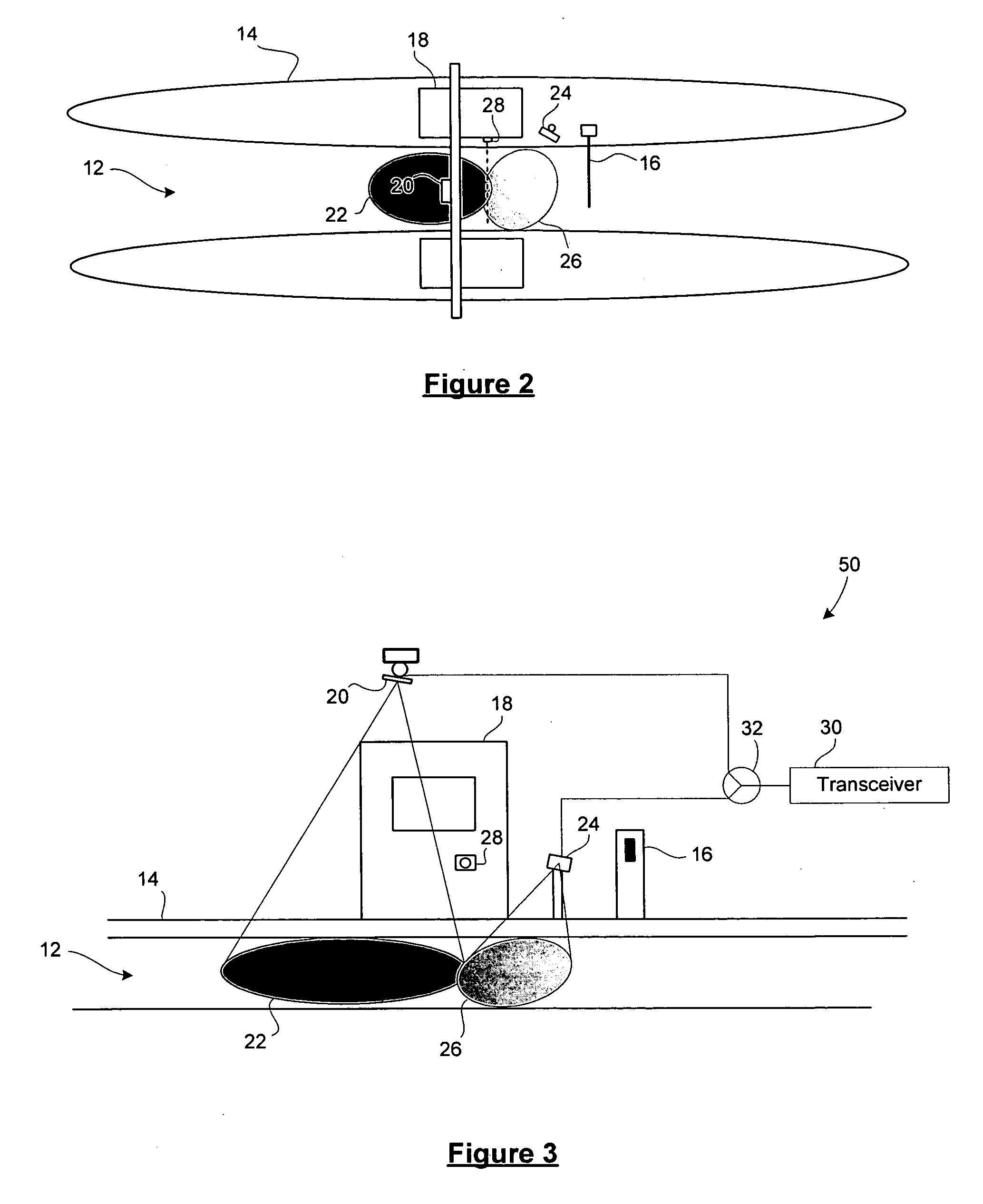
"The present invention provides an improved electronic toll collection system for vehicles in laneways. The system includes two lane-based antennas per laneway, with one antenna positioned overhead and one positioned at a side of the laneway. The system also includes a transaction processing system for conducting toll transaction communications with a vehicle-mounted transponder through one of the two antennas. The technical effects of the invention include improved communication with the vehicle-mounted transponder, increased efficiency in toll collection, and improved user experience."

Problems solved by technology

The license plate transponder is less well adapted for communications with an overhead gantry than the windshield transponder.
In addition, the license plate transponder may encounter multipath problems due to reflections off of the road surface.
These multipath problems can result in signal cancellation at certain mounting heights

Method used


Image

  • Electronic toll collection system
  • Electronic toll collection system
  • Electronic toll collection system

Examples


Embodiment Construction

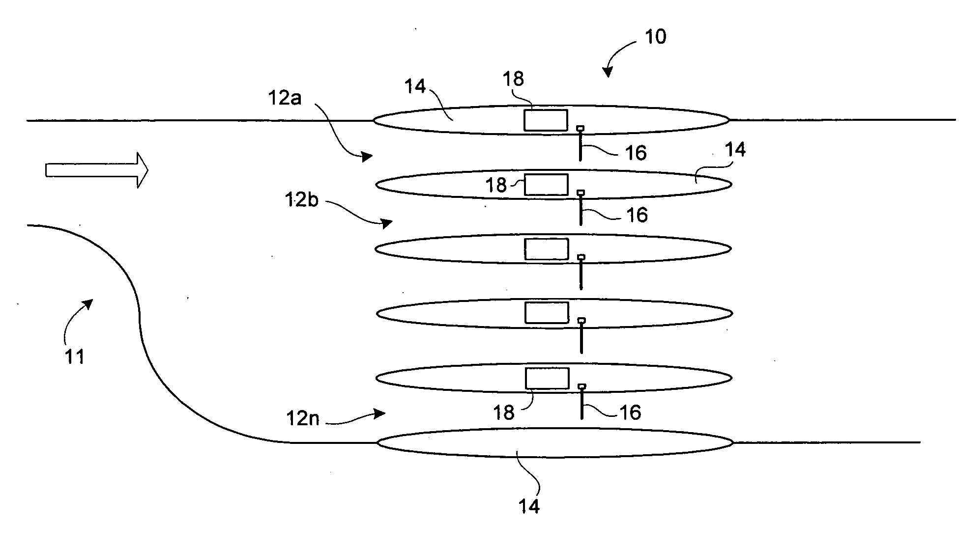
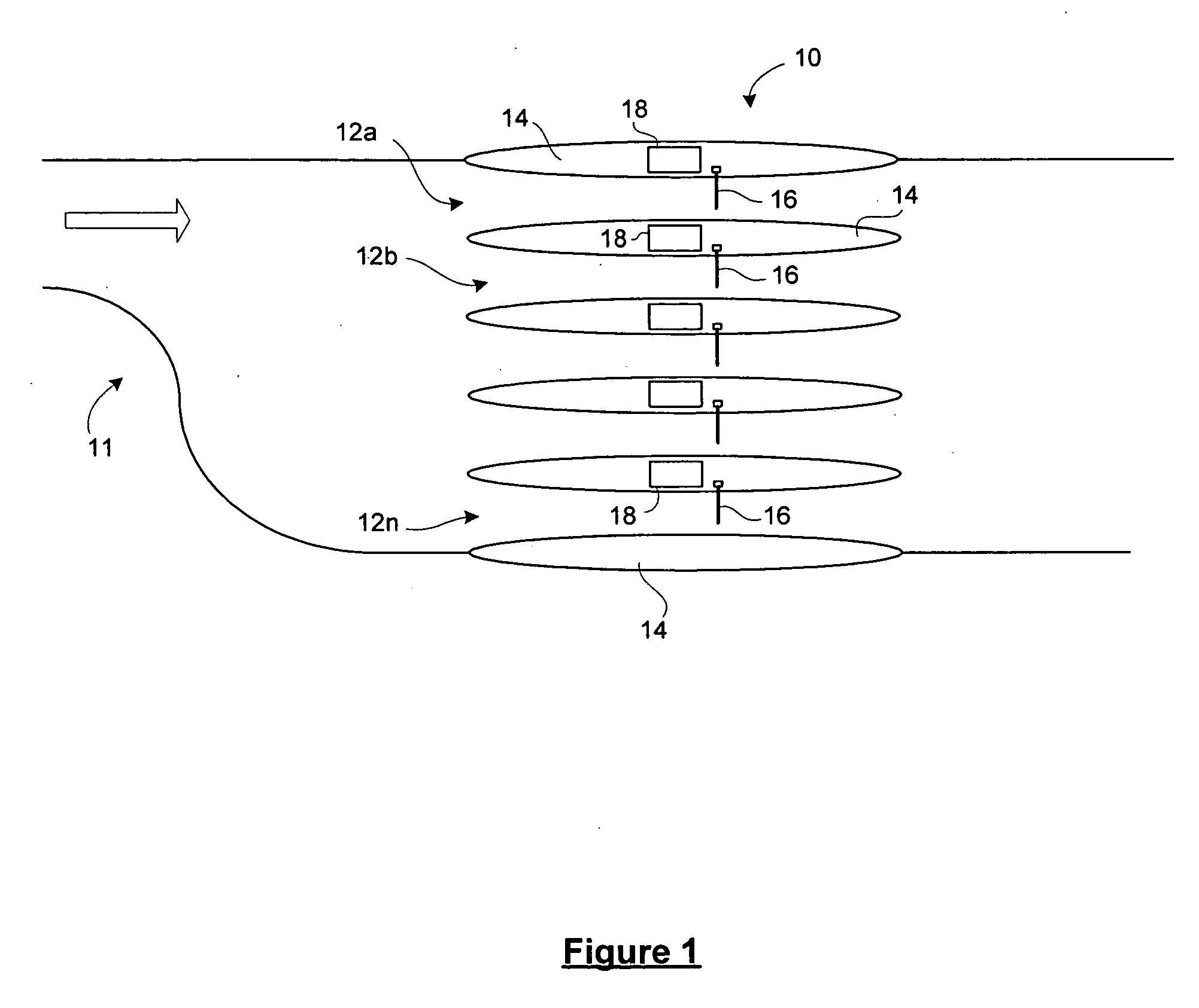
[0018] Reference is first made to FIG. 1, which shows a multi-lane roadway 11 containing a toll plaza 10. As indicated in FIG. 1, traffic flow for the multi-lane roadway 11 is from left to right in the diagram. Vehicles entering the widened portion of the multi-lane roadway 11 proceed to the toll plaza 10, wherein the vehicle is required to pay a toll before exiting the toll plaza 10.

[0019] It will be understood that, as described in U.S. Pat. No. 6,661,352, the toll plaza 10 may incorporate a wide area communications zone prior to the lane-based communications zone described below.

[0020] The toll plaza 10 includes a set of individual lanes 12a, 12b, . . . 12n separated by islands 14. Each individual lane 12 may have an associated barrier 16, such as a pivotable arm barrier to prevent drivers from proceeding through the toll plaza 10 prior to payment of the toll. It will be understood that the toll plaza 10 may have an additional or alternative indicator, such as a traffic light, ...


PUM


Abstract

An improved electronic toll collection system having two lane-based antennas per laneway. The antennas include an overhead antenna and a side mount antenna. The side mount antenna is disposed so as to communicate especially with license plate transponders. The two antennas are coupled to a transaction processing system for conducting toll transaction communications with a vehicle-mounted transponder through one of the two antennas.

Description

FIELD OF THE INVENTION [0001] The present invention relates to radio frequency (RF) electronic toll collection. BACKGROUND OF THE INVENTION [0002] Electronic toll collection systems conduct toll transactions electronically using RF communications between a vehicle-mounted transponder (a “tag”) and a stationary toll plaza transceiver (a “reader”). An example of an electronic toll collection system is described in U.S. Pat. No. 6,661,352 issued Dec. 9, 2003 to Tiernay et al., and owned in common with the present application, the contents of which are hereby incorporated by reference. Typical electronic toll collection systems provide for toll plazas having reader antennas located above the toll road mounted on an overhead gantry or other support structure. The overhead antennas are directional and are intended to communicate with transponders or tags passing beneath them on the toll road. [0003] A vehicular transponder or tag is typically one of two types: a windshield transponder or ...

Claims


Application Information

Patent Timeline
Patent Type & Authority Applications(United States)
IPC IPC(8): G08G1/065G07B15/06
CPCG07B15/063G08G1/017
Inventor TANG, WAI-CHEUNGHO, THUA VAN
Owner MARK IV INDS
Learn More