Ground based inflatable antenna

a ground-based, inflatable technology, applied in the direction of collapsible antennas, antenna details, antennas, etc., can solve the problems of large antenna dish instability, difficult implementation of portable antennas, and the amount of weight and storage space required by such an antenna system

Inactive Publication Date: 2006-04-06
SRS TECH
View PDF3 Cites 15 Cited by
  • Summary
  • Abstract
  • Description
  • Claims
  • Application Information

AI Technical Summary

Problems solved by technology

However, a large antenna dish can become unstable when exposed to environmental conditions such as wind.
While this approach works for fixed location antennas, it is difficult to implement for portable antennas. FIG. 1 shows an example of a prior art deployable satellite communications antenna 10.
The amount of weight and storage space required by such an antenna system is an impediment to quick and easy movement and assembly in locations that need satellite communications.
While smaller antennas are more portable, their performance is not as good as that of larger antennas.
However, because of the structural weakness resulting from their light weight, they are typically unsuitable for atmospheric use.

Method used


Image

  • Ground based inflatable antenna
  • Ground based inflatable antenna
  • Ground based inflatable antenna

Examples


Embodiment Construction

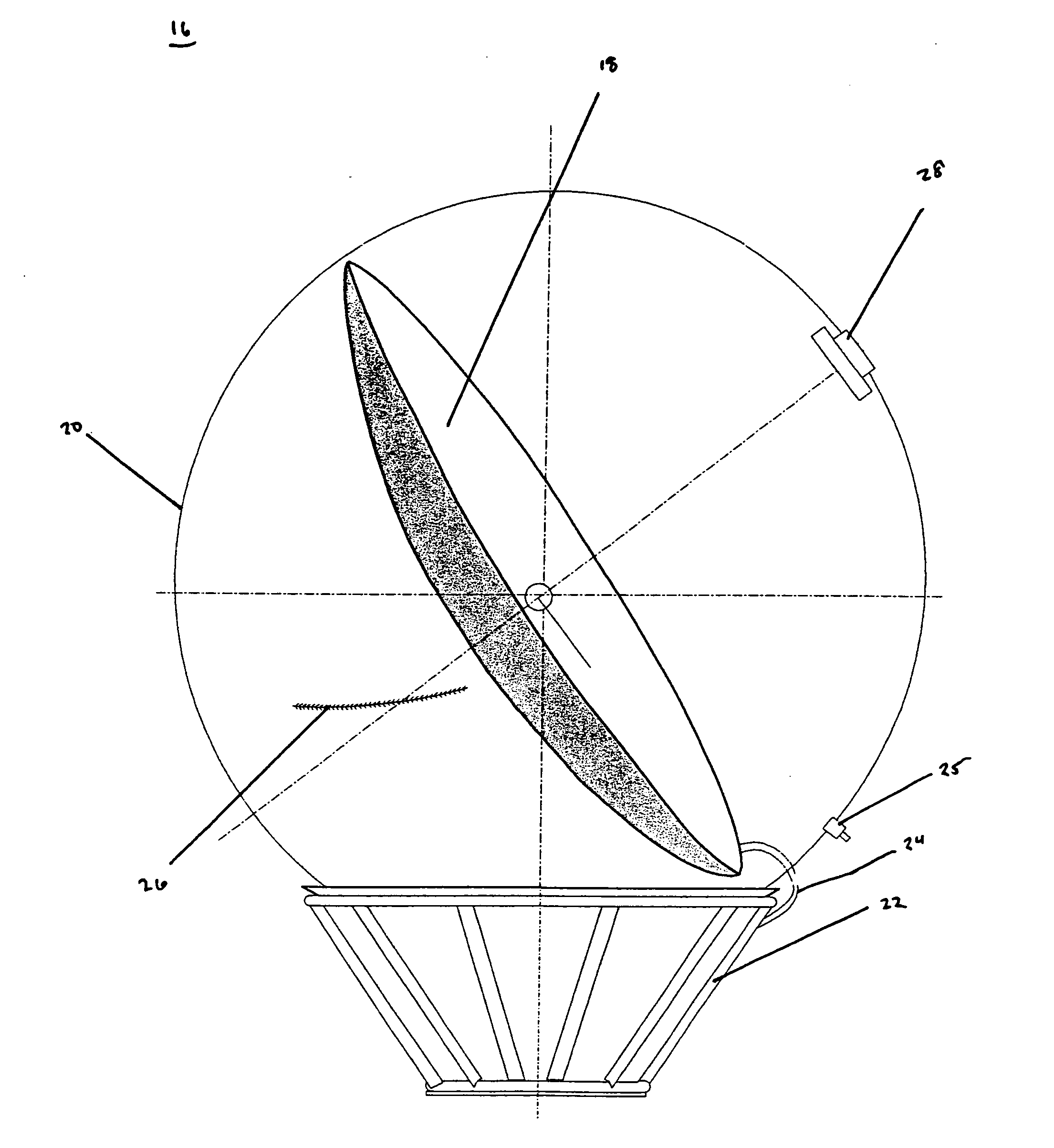
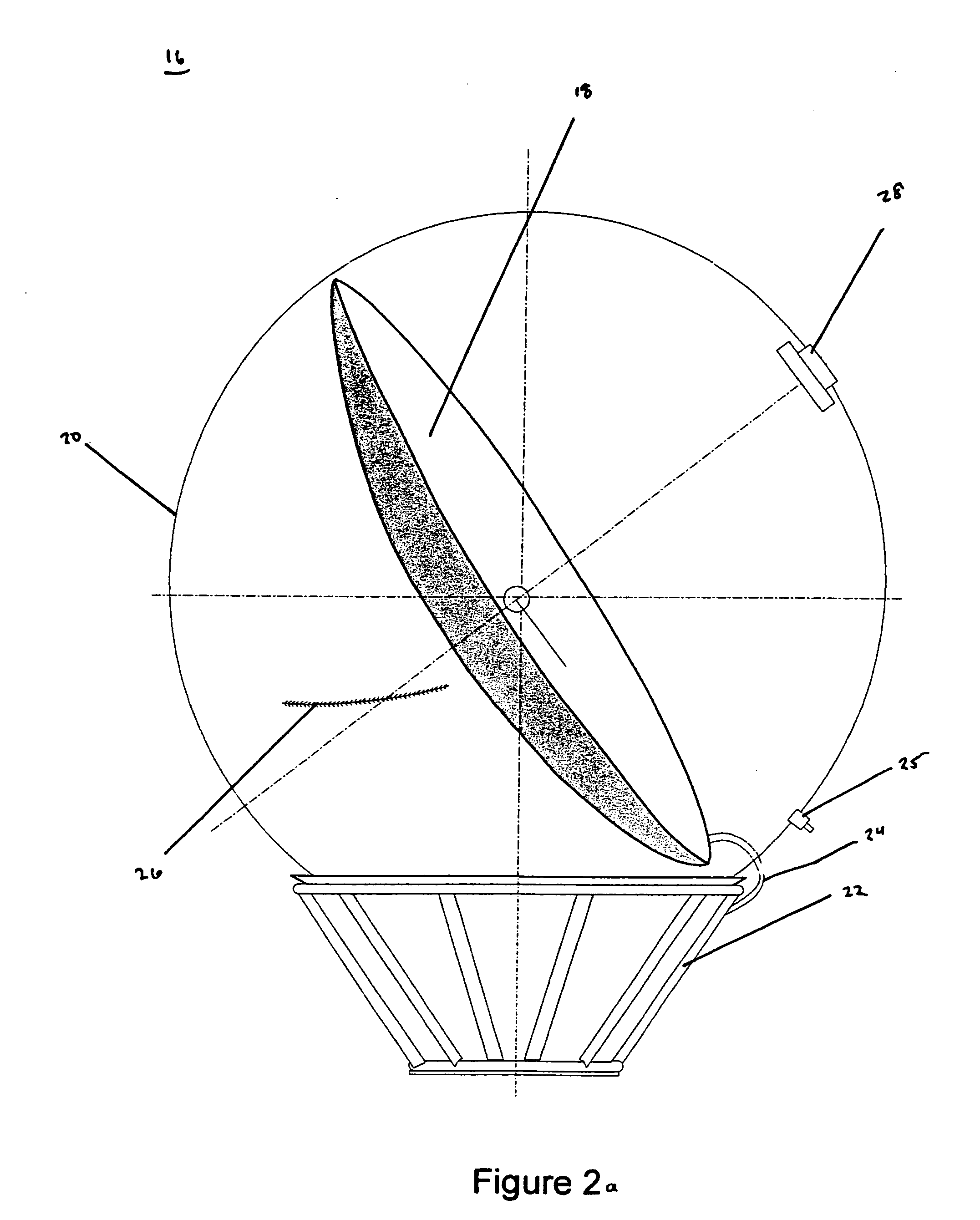
[0033] A ground-based inflatable antenna that may be used as part of a portable satellite communications system has been developed. The antenna may also be used for other applications such as radar or line-of-sight communications. FIG. 2a shows a cross-section view of an example of an antenna 16 in accordance with one embodiment of the present invention. The antenna includes an inflatable lenticular or “dish”18 that is oriented towards a target such as a satellite. The dish 18 is surrounded by an inflatable radome 20. The radome 20 is a spherical-shaped cover that provides protection for the dish 18 from environmental elements such as wind, etc. This allows the dish 18 to maintain proper alignment towards its target. The radome 20 is constructed of a flexible material or a membrane that is stable in ultraviolet light. A membrane is a thin, pliable sheet of natural or synthetic material that is supported by either mechanical tension or a pressure differential. The material should not...


PUM


Abstract

The invention is a ground based inflatable antenna system. The antenna system includes an inflatable lenticular dish. The dish is enclosed in an inflatable radome. The inflatable radome stabilizes the orientation of the dish and protects it from environment conditions such as wind.

Description

CROSS-REFERENCE TO RELATED APPLICATIONS [0001] This application is a Continuation Application of U.S. patent application Ser. No. 10 / 429,442 titled “Inflatable Antenna” that was filed on May, 05, 2003.BACKGROUND OF INVENTION [0002] 1. Field of the Invention [0003] The invention relates generally to an antenna. More specifically, the present invention relates to an inflatable antenna that is stabilized with a radome. [0004] 2. Background Art [0005] Antennas tend to be very sensitive elements of communications or radar systems. Correct alignment of the dish portion of the antenna is critical to proper operation. However, a large antenna dish can become unstable when exposed to environmental conditions such as wind. Typical solutions involve bracing and reinforcing the antenna system with a heavy support structure. While this approach works for fixed location antennas, it is difficult to implement for portable antennas. FIG. 1 shows an example of a prior art deployable satellite commun...

Claims


Application Information

Patent Timeline
Patent Type & Authority Applications(United States)
IPC IPC(8): H01Q1/42H01Q1/08H01Q3/26H01Q15/16H01Q19/10
CPCH01Q1/081H01Q3/26H01Q15/163H01Q19/10
Inventor GIEROW, PAULLAUE, GREGORY P.CLAYTON, WILLIAM R.HACKETT, RONALD D.
Owner SRS TECH
Why Eureka
Try Eureka