
Metamaterial radome/isolator

a technology of radome and isolator, which is applied in the direction of antenna details, radiating element housings, antennas, etc., can solve the problems of little impact on reflection, and achieve the effects of less acute diffraction, stable frequency range, and low reflection

Active Publication Date: 2011-08-18
RAYTHEON CO
View PDF14 Cites 50 Cited by
  • Summary
  • Abstract
  • Description
  • Claims
  • Application Information

AI Technical Summary

Benefits of technology

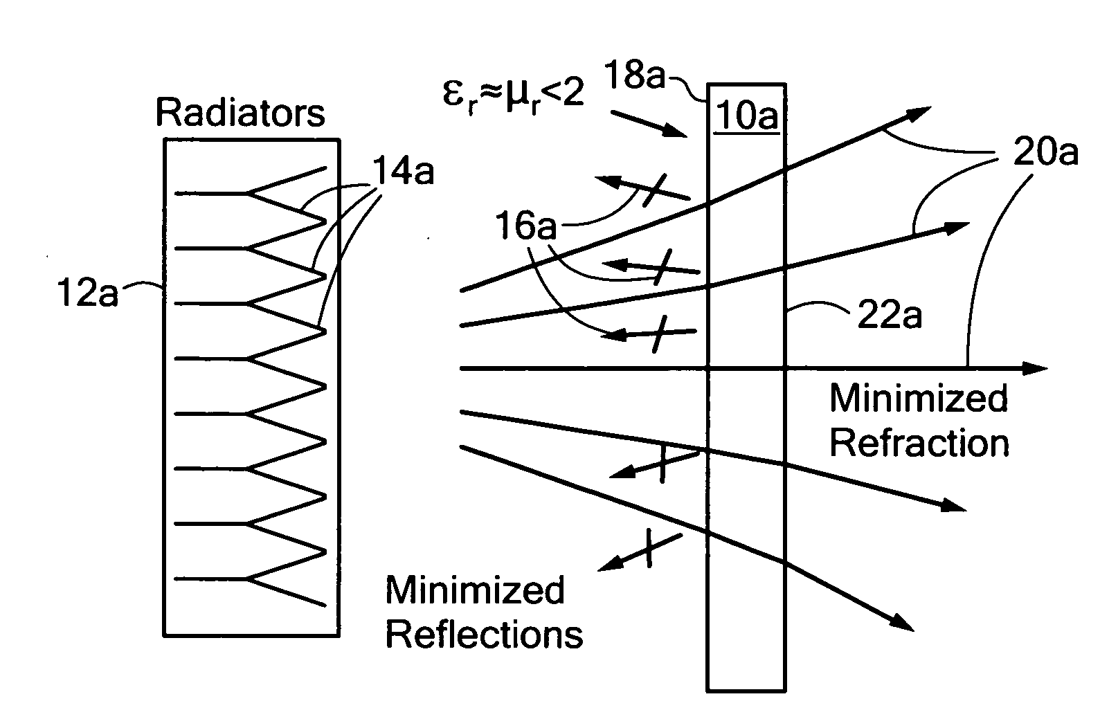
[0004]In accordance with various aspects of the subject invention in at least one embodiment the invention presents an improved metamaterial radome or isolator which provides lower reflection, less acute diffraction and operates in a more stable frequency range.

Problems solved by technology

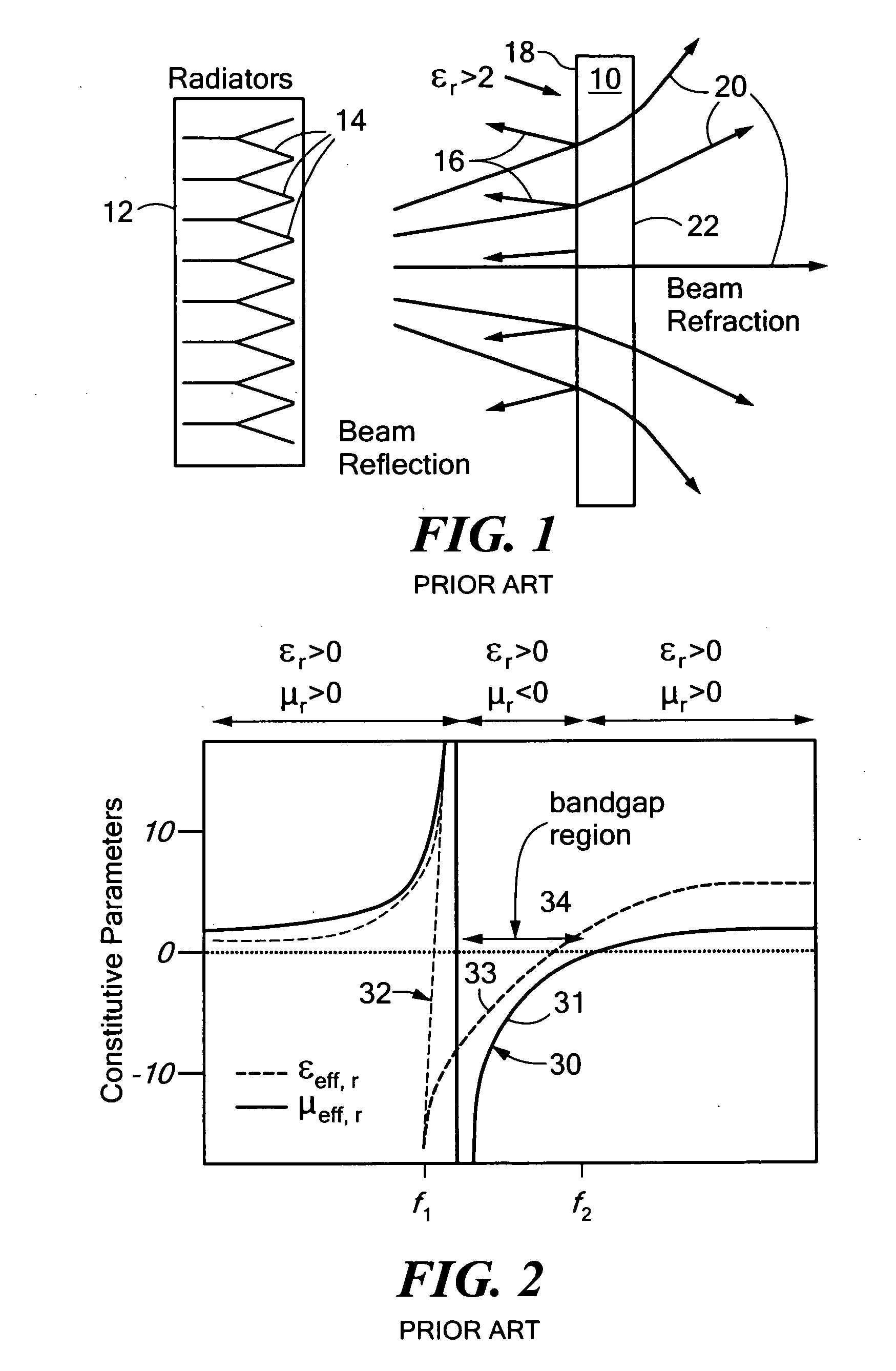
Existing metamaterial solutions have demonstrated the ability to correct refraction in radomes in a variety of ways, but all such techniques are inherently narrowband (<1%) and have little impact on the reflection at the radome interface caused by characteristic impedance mismatch.

Method used


Image

  • Metamaterial radome/isolator
  • Metamaterial radome/isolator
  • Metamaterial radome/isolator

Examples


Embodiment Construction

[0022]Aside from the preferred embodiment or embodiments disclosed below, this invention is capable of other embodiments and of being practiced or being carried out in various ways. Thus, it is to be understood that the invention is not limited in its application to the details of construction and the arrangements of components set forth in the following description or illustrated in the drawings. If only one embodiment is described herein, the claims hereof are not to be limited to that embodiment. Moreover, the claims hereof are not to be read restrictively unless there is clear and convincing evidence manifesting a certain exclusion, restriction, or disclaimer.

[0023]The purpose of a radome is to provide mechanical protection of the radiating elements and any related sub-system components from the external operational environment, to include humidity, particulates, chemical contaminates, oxidation, temperature variations, and ambient radiation.

[0024]Because the dielectric material...


PUM


Abstract

A metamaterial radome / isolator system includes a radiation source for providing a radiation beam through the radome / isolator having a frequency beyond the bandgap region where the metamaterial permittivity and permeability are both positive and the metamaterial medium has a low, matched relative permittivity and relative permeability.

Description

FIELD OF THE INVENTION[0001]This invention relates to a metamaterial radome or isolator.BACKGROUND OF THE INVENTION[0002]The current state of the art in radome design features low loss tangent, low ∈r metamaterials such as Teflon or microwave laminates. Because the dielectric materials comprising the radome have positive permittivity greater than one (typically, greater than 2.1), the radome reduces the transmitted power by reflecting energy at the material interface, and refracts incident waves ultimately corrupting the beam shape.[0003]Existing metamaterial solutions have demonstrated the ability to correct refraction in radomes in a variety of ways, but all such techniques are inherently narrowband (<1%) and have little impact on the reflection at the radome interface caused by characteristic impedance mismatch.SUMMARY OF THE INVENTION[0004]In accordance with various aspects of the subject invention in at least one embodiment the invention presents an improved metamaterial rad...

Claims


Application Information

Patent Timeline
Patent Type & Authority Applications(United States)
IPC IPC(8): H01Q1/42H01Q15/02
CPCH01Q1/42H01Q15/02H01Q1/422
Inventor MORTON, MATTHEW A.SHOGHI, PAYAMHERNDON, MARY K.
Owner RAYTHEON CO
Learn More