System and method for antenna alignment

a technology of antenna alignment and system, applied in the field of wireless communication systems, can solve the problems of affecting the search effect of other signals, wasting considerable time in searching for other signals, and distorted measuremen

Inactive Publication Date: 2012-07-12
MCCOWN JAMES CHARLES
View PDF4 Cites 54 Cited by
  • Summary
  • Abstract
  • Description
  • Claims
  • Application Information

AI Technical Summary

Benefits of technology

[0011]Another embodiment of a parabolic antenna for radio frequency communications is disclosed. The parabolic antenna may include a parabolic dish. The parabolic antenna may further include a feedhorn socket coupled to the parabolic dish. The parabolic antenna may further include a radome coupled to the parabolic dish, the radome including an optically transparent window. The parabolic antenna may further include the feedhorn socket configured to selectively receive a spotting scope, such that the spotting scope is coaxially secured with respect to the optically transparent window in the radome. The parabolic antenna may further include the feedhorn socket further configured to selectively receive a feedhorn assembly.

Problems solved by technology

Of course, there are drawbacks with this approach.
First, the transmitting antenna must be radiating (power switched on) which may cause a hazardous situation (electrical power and electromagnetic radiation) for the person(s) making the adjustments to the aiming of the transmitting antenna and for the person(s) at the receiving antenna.
Second, it is possible to erroneously lock onto a strong side lobe, or have to deal with signal reflections from the surroundings which may affect the measured field strength, distorting measurement results and causing aiming errors.
Third, using such an aiming approach requires two installation teams, each placed in one end of the radio link for measuring and aiming the respective antennas.
Fourth, if both antennas are highly directional (the normal case), considerable time can be expended in searching for the other signal as at least one of the two antennas must be aligned to the correct path within a few degrees before any signal is detected from either end.
For this reason, there is opportunity for alignment error depending on how well the optical scope line of sight correlates with the actual direction of the main lobe of the transmitting antenna.

Method used


Image

  • System and method for antenna alignment
  • System and method for antenna alignment
  • System and method for antenna alignment

Examples


Embodiment Construction

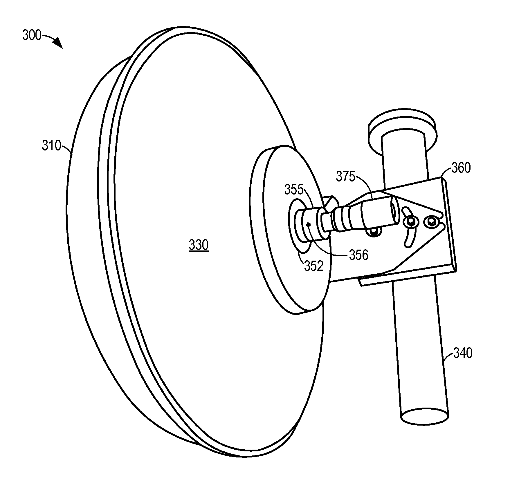
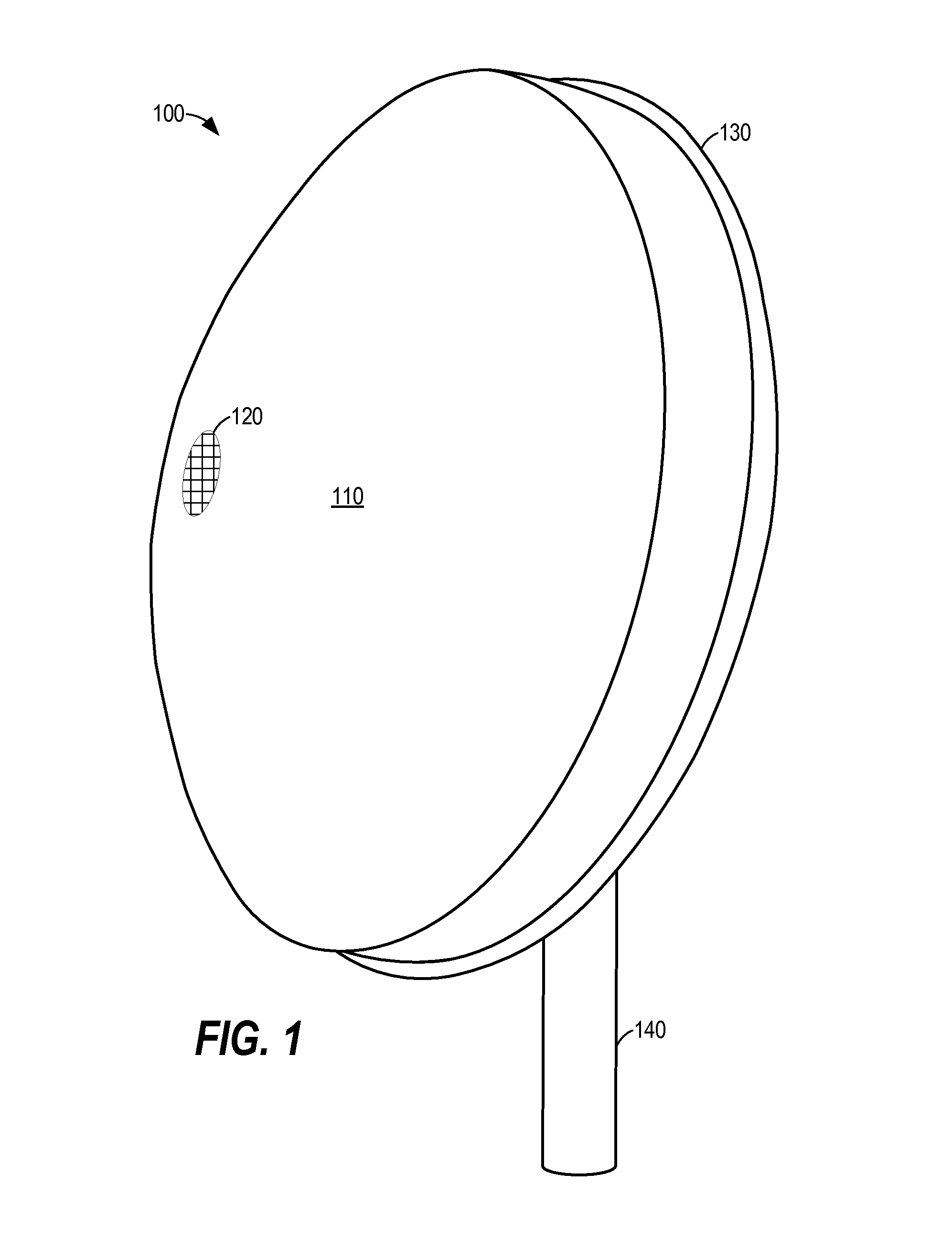
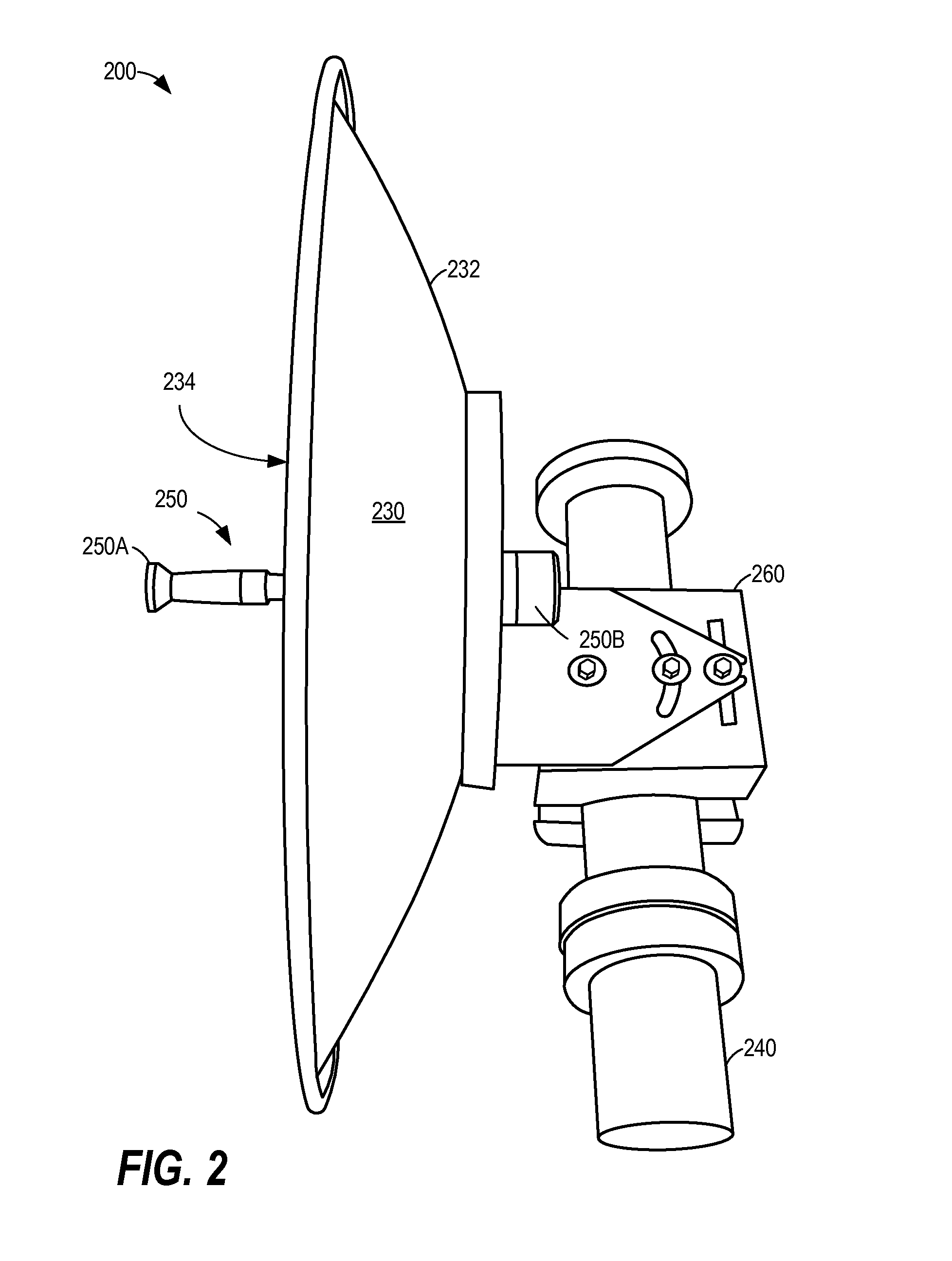
[0028]The present disclosure provides various systems and methods for visually aligning an antenna using a spotting scope mounted in a feedhorn socket in place of a feedhorn assembly. According to various embodiments, a parabolic antenna may be configured to transmit and / or receive radio signals in order to provide wireless communication between two points. According to various embodiments, an antenna may include a parabolic dish, a radome, a feedhorn assembly, and an outdoor radio unit or transmission line consisting of a coaxial cable or waveguide. According to various embodiments, the feedhorn assembly may be selectively removed and replaced with a spotting scope during alignment. Accordingly, a user may visually align the parabolic antenna by looking through the spotting scope mounted in the feedhorn socket.

[0029]It will be understood that the term “spotting scope”, as used herein, is synonymous with the terms “telescopic sight” or “riflescope”, and refers generally to a telesco...


PUM


Abstract

According to various embodiments, a parabolic antenna may include a radome with an optically transparent window. The parabolic antenna may include a feedhorn socket configured to receive a feedhorn assembly. The feedhorn socket may also be configured to receive a spotting scope. According to various embodiments, the spotting scope may be mounted in place of the feedhorn assembly and used to optically align the parabolic antenna with respect to a distant target. The optically transparent window positioned in the radome may allow a user to see through the radome. Once aligned, the spotting scope may be removed from the feedhorn socket. A feedhorn assembly may then be secured in the feedhorn socket and a radio unit coupled thereto for radio frequency transmission.

Description

CROSS-REFERENCE TO RELATED APPLICATIONS[0001]This U.S. nonprovisional patent application claims benefit and priority under 35 U.S.C. §119(e) of the filing of U.S. provisional patent application No. 61 / 430,824 filed on Jan. 7, 2011, titled “SYSTEM AND METHOD FOR ANTENNA ALIGNMENT”, the contents of which are expressly incorporated herein by reference for all purposes as if fully set forth herein.BACKGROUND OF THE INVENTION[0002]1. Field of the Invention[0003]This disclosure generally relates to antennas for wireless communication systems. More particularly, this disclosure describes systems and methods for visually aligning an antenna using a spotting scope selectively mounted in place of a feedhorn assembly.[0004]2. Description of Related Art[0005]Wireless radio links are commonly used to transmit data from one location to another, e.g., from one building to another building in a computer network or data link. This wireless transmission of data is frequently bidirectional. Such radio...

Claims


Application Information

Patent Timeline
Patent Type & Authority Applications(United States)
IPC IPC(8): G01B11/26H01Q1/42
CPCH01Q15/16H01Q1/1264
Inventor MCCOWN, JAMES CHARLES
Owner MCCOWN JAMES CHARLES
Why Eureka
Try Eureka