
Communication system with broadband antenna

a broadband antenna and communication system technology, applied in the field of wireless communication systems, can solve the problems of limited field of view, low efficiency, and limit the ability of satellite signals to be received

Inactive Publication Date: 2006-04-06
ASTRONICS AEROSAT CORP
View PDF14 Cites 21 Cited by
  • Summary
  • Abstract
  • Description
  • Claims
  • Application Information

AI Technical Summary

Problems solved by technology

However, each of these systems may suffer from limited field of view or low efficiency that limit their ability to receive satellite signals.
In particular, these conventional systems may lack the performance required to receive satellite signals where either the signal strength is low or noise is high, for example, signals from low elevation satellites.

Method used


Image

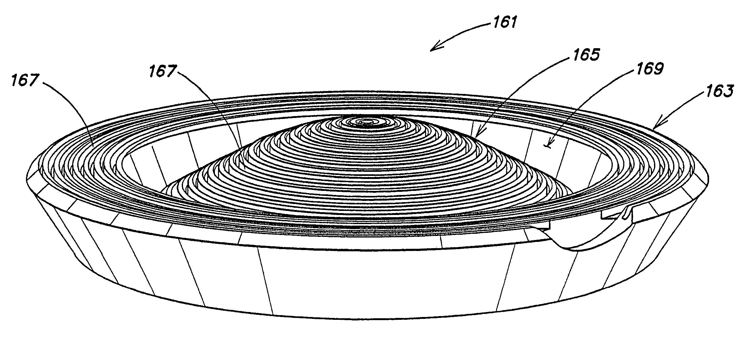
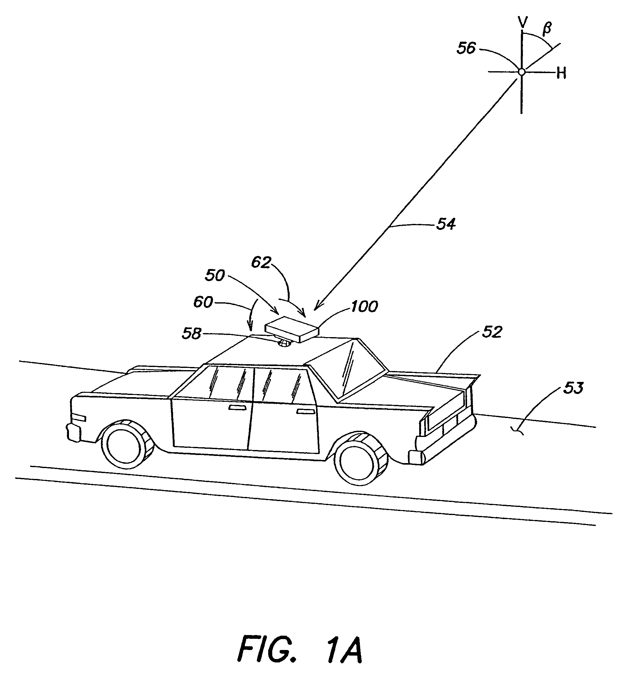
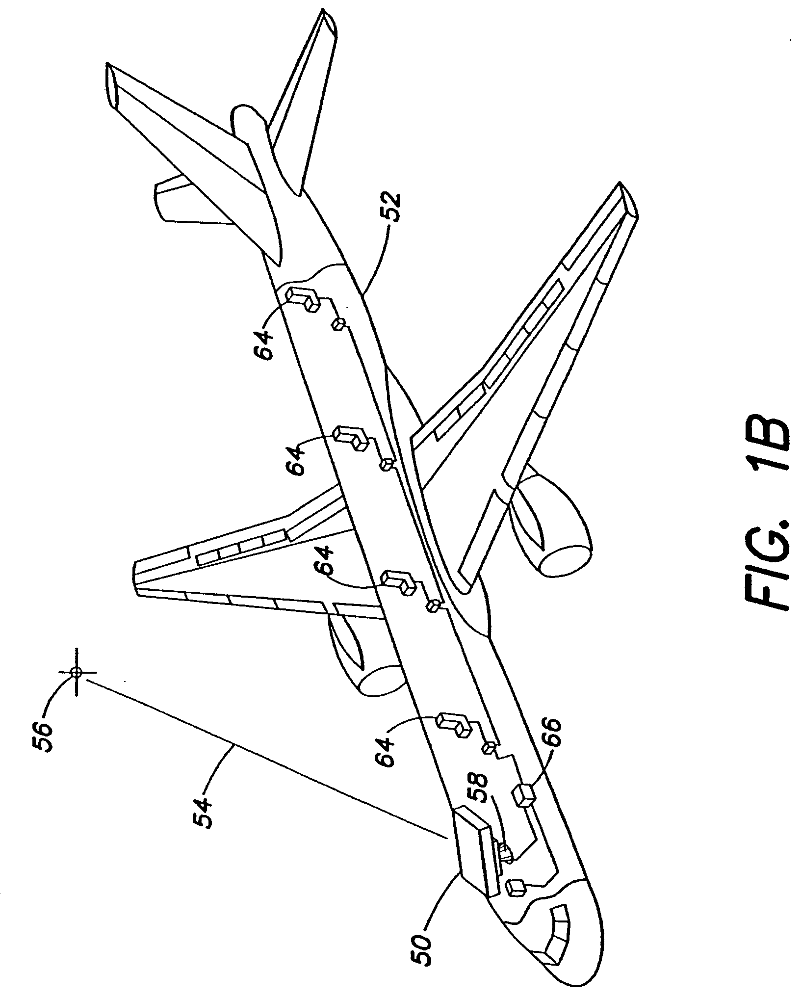
  • Communication system with broadband antenna
  • Communication system with broadband antenna
  • Communication system with broadband antenna

Examples


Embodiment Construction

[0041] A communication system described herein includes a subsystem for transmitting and receiving an information signal that can be associated with a vehicle, such that a plurality of so-configured vehicles create an information network, e.g., between an information source and a destination. Each subsystem may be, but need not be, coupled to a vehicle, and each vehicle may receive the signal of interest. In some examples, the vehicle may be a passenger vehicle and may present the received signal to passengers associated with the vehicle. In some instances, these vehicles may be located on pathways (i.e., predetermined, existing and constrained ways along which vehicles may travel, for example, roads, flight tracks or shipping lanes) and may be traveling in similar or different directions. The vehicles may be any type of vehicles capable of moving on land, in the air, in space or on or in water. Some specific examples of such vehicles include, but are not limited to, trains, rail ca...


PUM


Abstract

A communication system including an antenna array with feed network coupled to communication electronics. In one example, a communication subsystem comprises a plurality of antennas each adapted to receive an information signal and a plurality of orthomode transducers coupled to corresponding ones of the plurality of antennas, each OMT is adapted to provide at a first component signal having a first polarization and a second component signal having a second polarization. The communication subsystem also comprises a feed network that receives the first component signal and the second component signal from each orthomode transducer and provides a first summed component signal at a first feed port and a second summed component signal at a second feed port, and a phase correction device coupled to the first and second feed ports and adapted to phase match the first summed component signal with the second summed component signal.

Description

REFERENCE TO RELATED APPLICATIONS [0001] This application is a divisional of, and claims priority under 35 U.S.C. §120 and §121 to, co-pending U.S. patent application Ser. No. 10 / 644,493, filed Aug. 20, 2003, now U.S. Pat. No. 6,950,073 which in turn claims priority under 35 U.S.C. §119(e) to U.S. Provisional application Ser. No. 60 / 405,080 entitled “Communication System with Broadband Antenna,” filed Aug. 20, 2002 and U.S. Provisional application Ser. No. 60 / 409,629 entitled “Communication System with Broadband Antenna,” filed Sep. 10, 2002, all of which are herein incorporated by reference in their entirety.BACKGROUND [0002] 1. Field of the Invention [0003] The present invention relates to wireless communication systems, in particular, to an antenna and communications subsystem that may be used on passenger vehicles. [0004] 2. Discussion of Related Art [0005] Many communication systems involve reception of an information signal from a satellite. Conventional systems have used many...

Claims


Application Information

Patent Timeline
Patent Type & Authority Applications(United States)
IPC IPC(8): H01Q15/08H01P1/161H01Q1/28H01Q1/32H01Q3/08H01Q13/02H01Q15/02H01Q19/06H01Q19/08H01Q21/08
CPCH01P1/161H01Q1/28H01Q1/32H01Q3/08H01Q13/02H01Q21/06H01Q19/08H01Q21/08H01Q13/0258H01Q15/242H01Q21/0037H01Q15/02H01Q15/08
Inventor CLYMER, RICHARDBARRETT, MICHAELBLANDA, FRANKKRIVICICH, ROBERTANDERSON, RICHARD B.FLANNERY, MATTHEW
Owner ASTRONICS AEROSAT CORP
Learn More