
Method to provide high availability in network elements using distributed architectures

a distributed architecture and network element technology, applied in the field of networks, can solve the problems of unable or practicable to provide redundant network elements at network ingress, and increasing the amount of bandwidth consumed by non-revenue traffi

Inactive Publication Date: 2006-04-06
INTEL CORP
View PDF8 Cites 85 Cited by
  • Summary
  • Abstract
  • Description
  • Claims
  • Application Information

AI Technical Summary

Problems solved by technology

This places higher and higher demands on the network elements that make up the network, such as switches, routers, etc.
However, in some instances, it is not possible or practicable to provide redundant network elements at network ingress and egress points (e.g., at the network border elements).
As might be expected, the greater the redundancy and size of a network, the greater the number of Hello messages used to reflect the change in network configuration, increasing the amount of bandwidth consumed by this non-revenue traffic.
Additionally, the failure or removal of a network element creates a significant problem with respect to message / data delivery.
Thus, if a network element goes down, all of the packets / cells that are currently stored on that element will be lost.
This consumes additional network bandwidth, and the delay may be aggravating to the recipient.
Worse yet, under unconfirmed delivery protocols, such as UDP (User Datagram Protocol), data corresponding to the lost packets is irretrievably lost.
For voice traffic, this situation will either create a gap in the telephone conversion, or drop the call completely.
The failure of a network element also causes packet routes to change (to avoid the failed element), typically loading the network elements employed for the alternate paths, adding delays to the packet delivery.
This produces bottlenecks that reduce the operational bandwidth of the network as a whole.

Method used


Image

  • Method to provide high availability in network elements using distributed architectures
  • Method to provide high availability in network elements using distributed architectures
  • Method to provide high availability in network elements using distributed architectures

Examples


Embodiment Construction

[0022] Embodiments of methods and apparatus for providing high reliability in network elements employing distributed architectures are described herein. In the following description, numerous specific details are set forth to provide a thorough understanding of embodiments of the invention. One skilled in the relevant art will recognize, however, that the invention can be practiced without one or more of the specific details, or with other methods, components, materials, etc. In other instances, well-known structures, materials, or operations are not shown or described in detail to avoid obscuring aspects of the invention.

[0023] Reference throughout this specification to “one embodiment” or “an embodiment” means that a particular feature, structure, or characteristic described in connection with the embodiment is included in at least one embodiment of the present invention. Thus, the appearances of the phrases “in one embodiment” or “in an embodiment” in various places throughout t...


PUM


Abstract

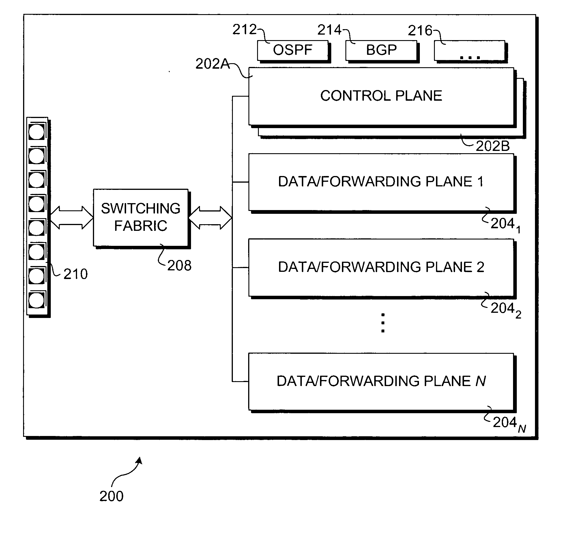
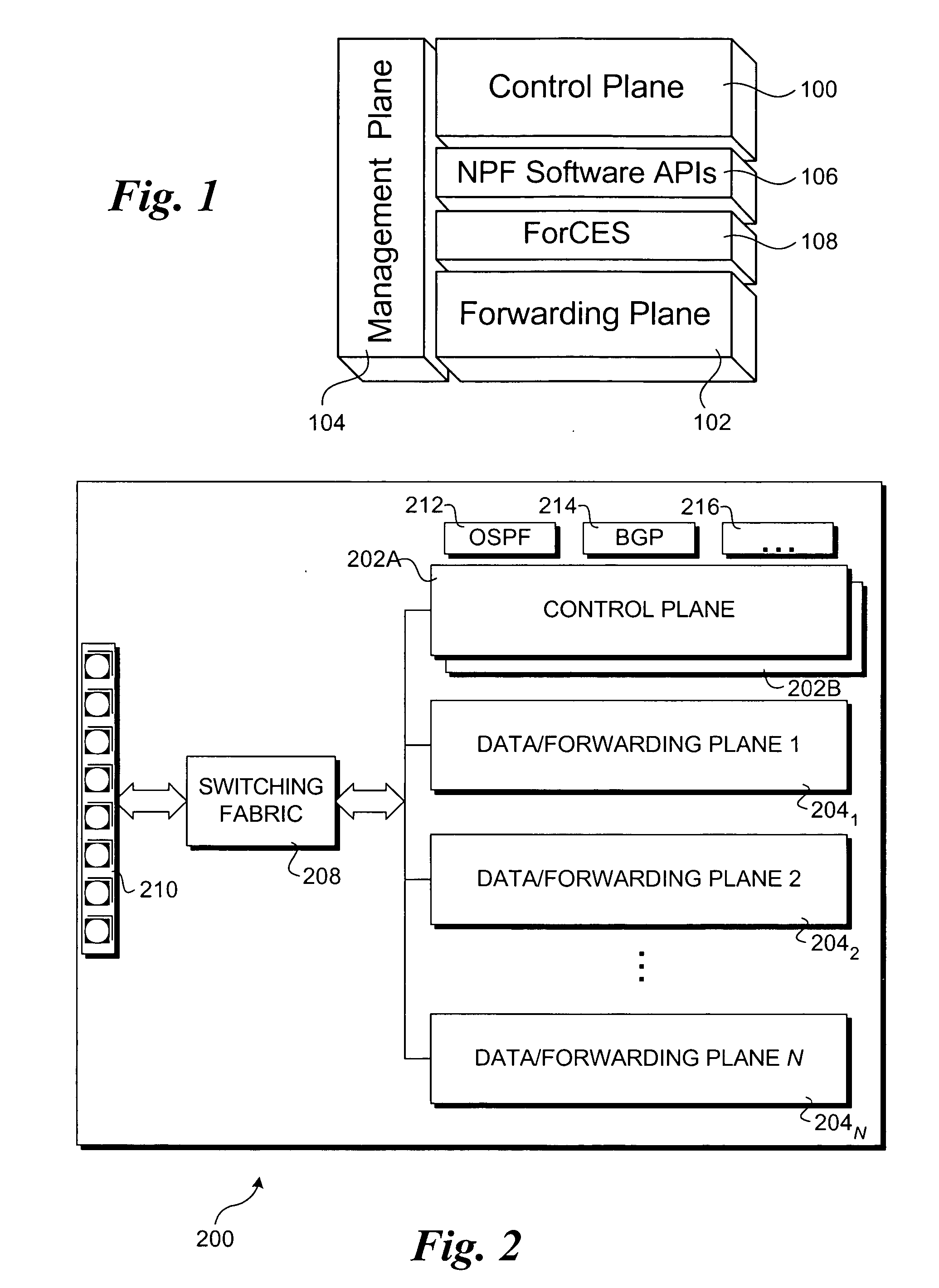
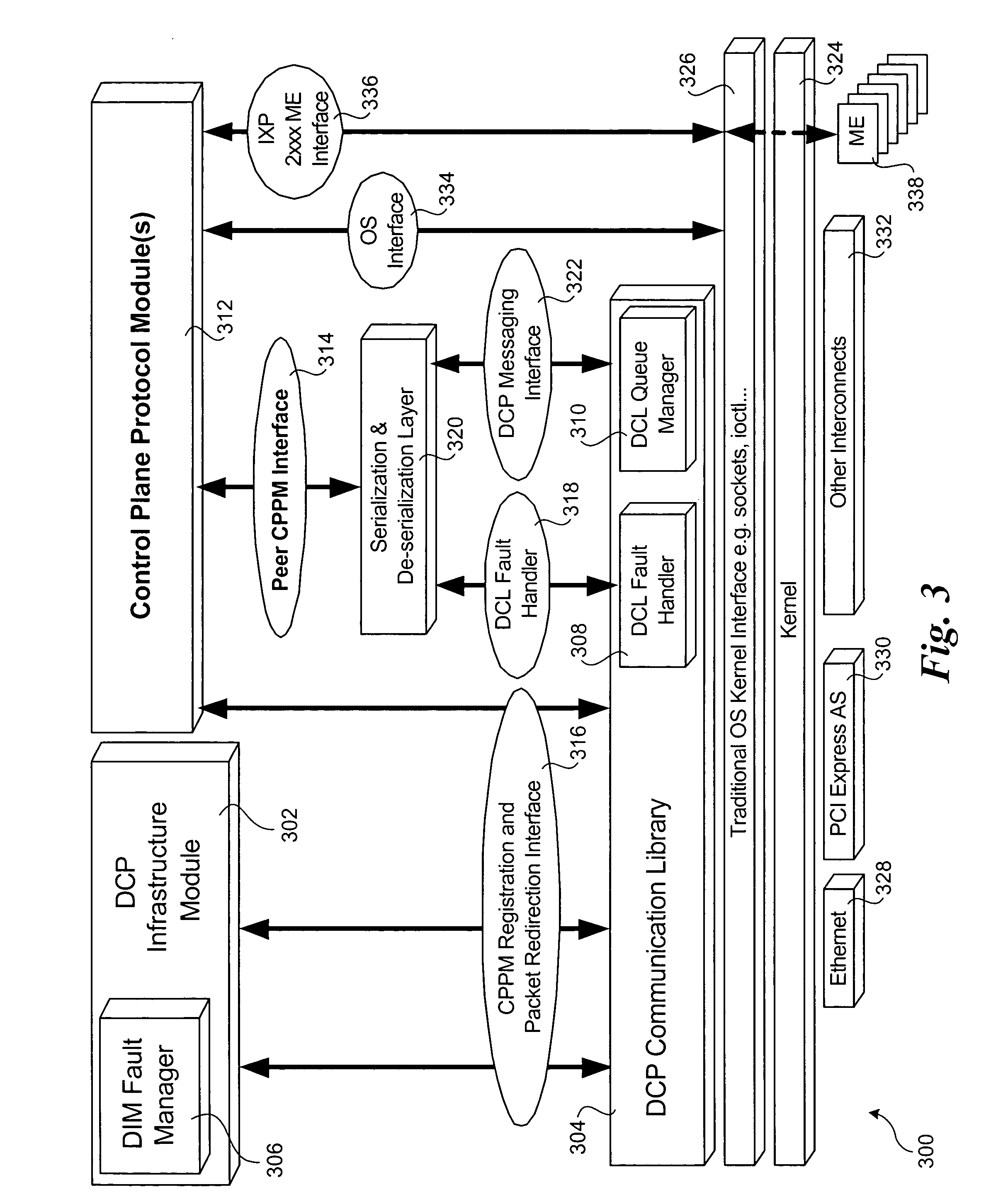
A method to provide high availability in network elements using distributed architectures. The method employs multiple software components that are distributed across data / forwarding plane and control plane elements in a network element. The software components in the data / forwarding plane include active and standby components. Components in the control plane are provided to communicate with the components in the data / forwarding plane. A keep-alive messaging mechanism is used to monitor operation of the various elements in the network element. Upon detection of a failure to a hardware or software component, the data / forwarding plane and / or control plane elements are reconfigured, as applicable, to replace a failed active component with a corresponding standby component. This enables the network element to be reconfigured in a manner that is transparent to other network elements, and provided high availability for the network element.

Description

FIELD OF THE INVENTION [0001] The field of invention relates generally to networks and, more specifically but not exclusively relates to techniques for providing high availability in network elements. BACKGROUND INFORMATION [0002] Continuation of the rapid growth in Internet and telecommunication usage experienced during the past decade is predicated on corresponding increases in network bandwidth. This places higher and higher demands on the network elements that make up the network, such as switches, routers, etc. The higher demands placed on networks, particularly high-bandwidth backbones, has lead to an increase in the number of network elements for a typical network, which, in turn, requires greater routing intelligence, longer routes (time-wise), and more sophisticated packet processing. [0003] Under a typical communication between two endpoints at different geographic locations, data is encapsulated in the form of packets (e.g., TCP / IP (Transmission Control Protocol over Inte...

Claims


Application Information

Patent Timeline
IPC IPC(8): H04L12/28
CPCH04L1/22H04L45/60
Inventor DEVAL, MANASIAHMED, SUHAILBALAKRISHNAN, SANTOSHKHOSRAVI, HORMUZDBAKSHI, SANJAY
Owner INTEL CORP
Learn More