Piezoelectric loudspeaker

a piezoelectric and loudspeaker technology, applied in the field of loudspeakers, can solve the problems of significant energy waste in generating sound with such a combination, and inefficient energy transducers, and achieve the effect of improving loudspeaker efficiency and increasing sound energy radiated

Inactive Publication Date: 2006-04-06
CROW ELECTRONICS ENG
View PDF8 Cites 2 Cited by
  • Summary
  • Abstract
  • Description
  • Claims
  • Application Information

AI Technical Summary

Benefits of technology

[0004] Preferred embodiments of the present invention provide a significant improvement in loudspeaker efficiency by mating a plane diaphragm, to which a piezoelectric disk has been bonded, to a preformed cover. The cover is a “one-piece” element comprising a section of a sphere, surrounded at a circumference of the section by an annulus. Mating such a cover with the bonded piezoelectric disk-diaphragm significantly increases the sound energy radiated by a loudspeaker at all frequencies at which the piezoelectric disk vibrates, compared to systems with no such cover.
[0005] The disk-diaphragm mates with the section of the sphere to form a substantially closed plano-convex volume. The plano-convex volume acts as a resonant cavity, and the cavity improves the efficiency of sound energy-electrical energy conversion. Conversion efficiency is also improved because of the larger surface area of the sphere section compared to both the piezoelectric disk and the diaphragm.
[0008] In order to form the loudspeaker, the actuator is fixed to the base of a labyrinth. The labyrinth provides a path for sound waves from the actuator to “open air” beyond the loudspeaker, and also acts to match the impedance of the actuator to the open air. The actuator is most preferably also fixed to the labyrinth in a push-fit manner, so that the complete loudspeaker may be quickly and simply assembled.

Problems solved by technology

However, the combination of the plane diaphragm and the piezoelectric disk is not an efficient energy transducer, and significant energy is wasted in generating sound with such a combination.

Method used


Image

  • Piezoelectric loudspeaker
  • Piezoelectric loudspeaker
  • Piezoelectric loudspeaker

Examples


Embodiment Construction

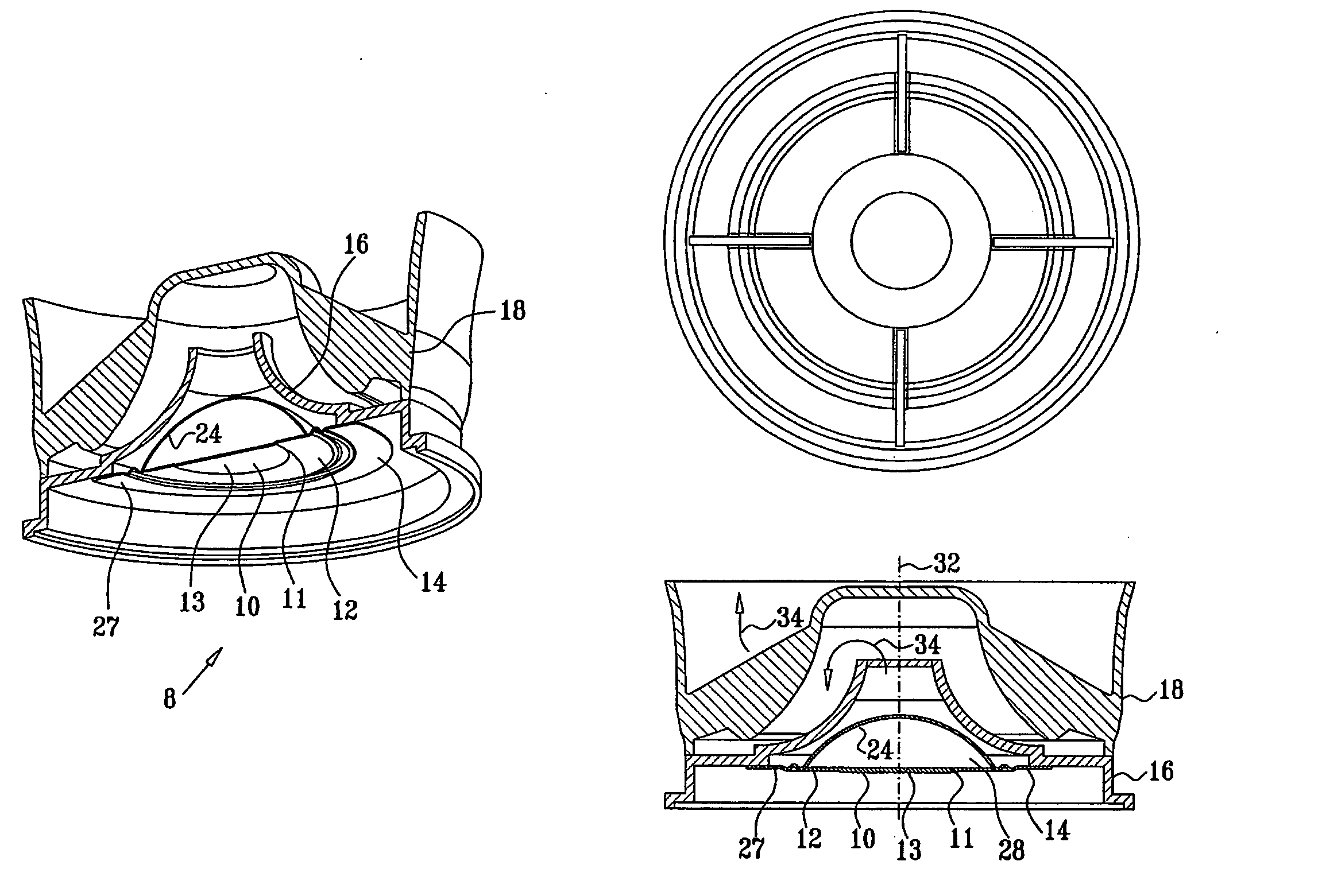
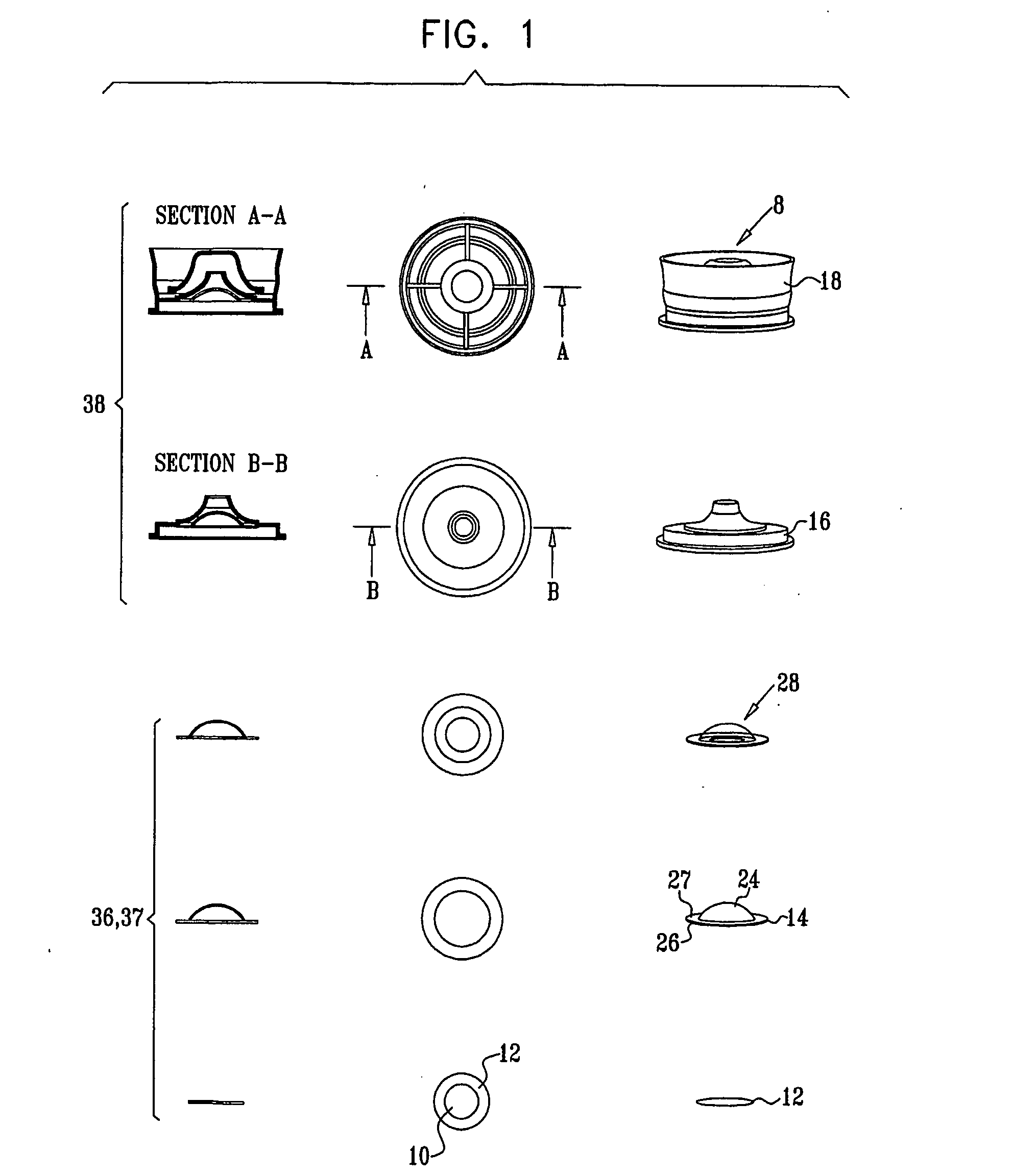
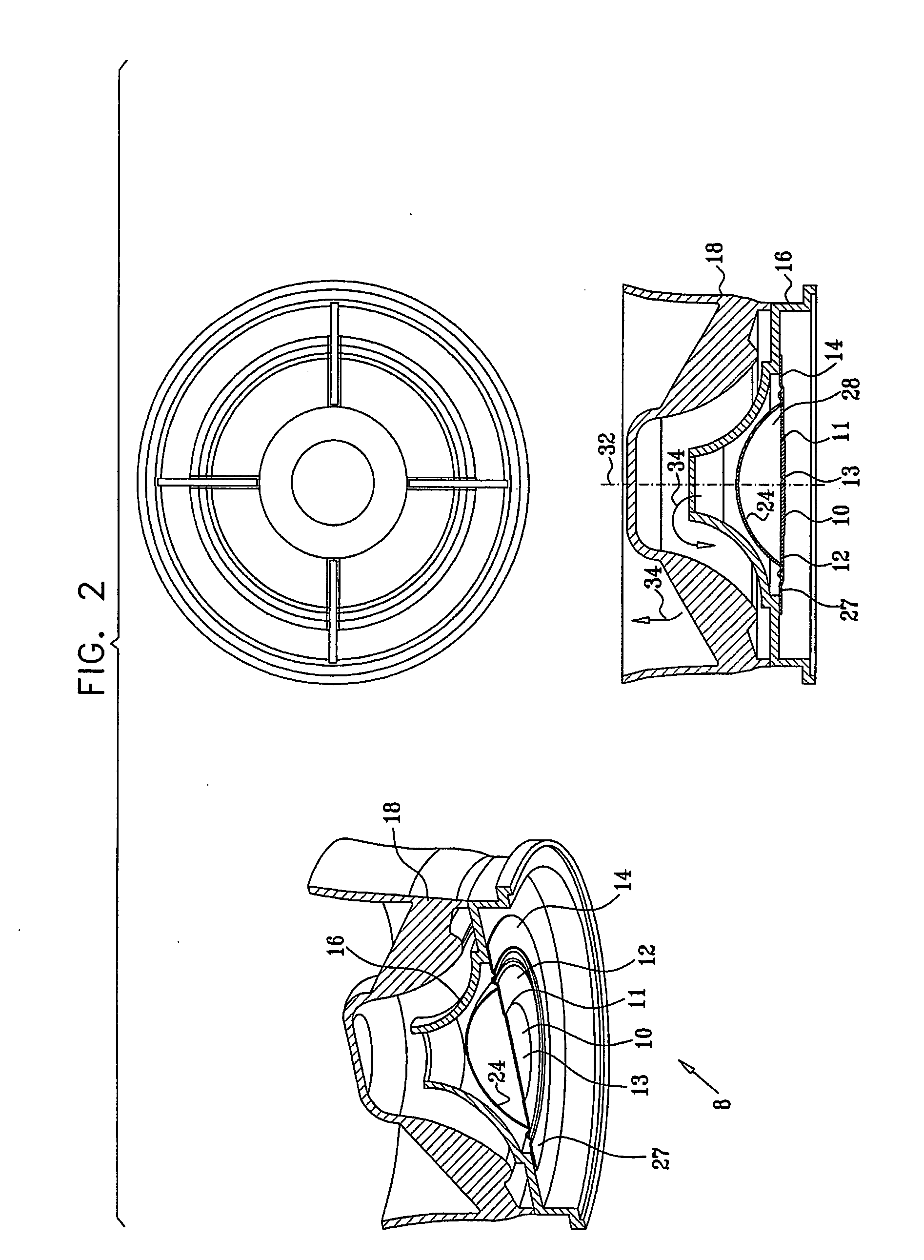
[0043]FIG. 1 is a schematic “exploded” illustration of a piezoelectric loudspeaker 8, and FIG. 2 shows schematic views of the piezoelectric loudspeaker as assembled, according to a preferred embodiment of the present invention. In the present disclosure, common identifying numbers in the figures correspond to common elements. An upper surface 11 of a piezoelectric disk 10 is bonded to an electrically conducting diaphragm 12, the diaphragm acting as a first electrode for the disk and acting also to increase an area from which sound energy is radiated. A second electrode (not shown for clarity in the figures) is coupled to a lower surface 13 of the piezoelectric disk.

[0044] A one-piece cover 14 is formed, consisting of a section 24 of a sphere surrounded by an annulus 26 which preferably has a substantially plane cross-section. Alternatively, cover 14 comprises section 24 surrounded by an annulus 27 having an at least partially sinusoidal cross-section, also termed herein a wavy cros...


PUM


Abstract

A loudspeaker (8), including a piezoelectric disk (10) having a first diameter and a diaphragm disk (12) which is fixed to the second diameter greater than the first diameter. The loudspeaker further includes a cover (14), consisting of a convex surface (24) bounded by an annulus (26, 27), which mates with the diaphragm disk to form a generally plano-convex volume (28) between the diaphragm disk and the cover. A labyrinth (16, 18) is fixedly coupled to a circumference of the annulus to provide a path (34) for sound waves.

Description

CROSS-REFERENCE TO RELATED APPLICATION [0001] This application claims the benefit of U.S. Provisional Patent Application 60 / 402,241, filed Aug. 8, 2002, which is incorporated herein by reference.FIELD OF THE INVENTION [0002] The present invention relates generally to loudspeakers, and specifically to loudspeakers using piezoelectric disks. BACKGROUND OF THE INVENTION [0003] Loudspeakers which use piezoelectric disks are well known in the art. In order to improve the performance of the disks, it is known to bond a plane diaphragm to the disk. Such a piezoelectric disk bonded to a plane diaphragm is described in U.S. Pat. No. 4,979,219 to Lin, whose disclosure is incorporated herein by reference. However, the combination of the plane diaphragm and the piezoelectric disk is not an efficient energy transducer, and significant energy is wasted in generating sound with such a combination. SUMMARY OF THE INVENTION [0004] Preferred embodiments of the present invention provide a significant ...

Claims


Application Information

Patent Timeline
Patent Type & Authority Applications(United States)
IPC IPC(8): H04R25/00H04R1/34H04R17/00H04R17/02
CPCH04R1/345H04R17/00H04R17/02H04R17/10
Inventor MELMAN, SHMUEL
Owner CROW ELECTRONICS ENG
Why Eureka
Try Eureka